BITREK CONNECT SYSTEM ORGANIZATION AND SETUP GUIDE
Terms and Definitions
CAN (Control Area Network) is a serial digital communication bus interface compliant with the international standard ISO 11898-1:2003. CAN bus is used for interconnection of various actuating electronic devices and sensors both in industrial automation systems and in automotive industry.
FMS - data packages of vehicle on-board information buses, corresponding to the document FMS-Standard Interface Description. FMS-Standard is an open FMS interface standard developed by the world's leading truck manufacturers.
J1939 is a communication and diagnostic network standard for various vehicles. Originally developed for trucks. The network created on the basis of J1939, as a channel level uses the communication bus CAN standard CAN 2.0b. Currently the J1939 standard is widely used in agricultural machinery, buses, and trucks.
Connect-Bus - telematic bus of the vehicle, which serves to connect all Connect system devices into a single network. Physically it is implemented on the basis of CAN interface. Connect-Bus information exchange protocol is based on J1939 protocol.
The term PGN (Parameter Group Number) is a parameter group number that defines the content of the corresponding CAN bus message according to J1939. The term PGN is used to refer to CAN bus messages.
Variable translated to Connect-Bus - A specific parameter in a Connect-Bus message. Each variable has a number of parameters, such as data length, data type, numerical value.
Protocol - A set of logical level conventions that allow connection and communication between two or more networked devices. These conventions define a uniform way of transmitting data and handling errors.
CONNECT SYSTEM Module - A module that is part of the Connect system and performs certain functions. Each module is connected to the Connect-Bus and communicates with other modules.
System Purpose
The Bitrek Connect system is designed to remotely track the location and condition of moving objects in real time using a variety of satellite tracking systems and data transmission via mobile communications. In addition, the system can receive, collect and process data from various additional equipment.
The Bitrek Connect system is designed to solve complex complex tasks. Depending on the additional modules connected to the system, different configurations of the Connect system can be created. Thus, tasks for different types of vehicles can be solved:
- tractors
- harvesters
- fuel tankers
- passenger vehicles
- cabs
- trains
- cranes
- refrigerators
- agricultural machinery
- construction machinery
It is also possible to gradually expand the system by adding new modules and connecting new sensors. There is no need to change existing equipment. In addition, it is possible to create unique developments and modifications of the modules connected to the system to order.
System organization
The basis of the system organization is the CAN-interface, which allows you to connect a large number of additional sensors to the system. The Bitrek Connect tracker does not have the usual set of digital interfaces, digital and analog inputs. Instead, it is equipped with one CAN interface (hereinafter referred to as Connect-Bus) and can be configured to receive information from various additional modules of the system. The modules, in turn, are made as separate devices connected to the Connect-Bus and can, depending on their purpose, process data from various sensors and transmit data to the bus.
The information sent by the modules to the system bus can be used not only by the tracker to send it to the server, but also by other devices in the Connect system. For example, the RL02 module (module for controlling the unloading of the harvester) can communicate directly with the BL01 module (module for identifying “Friend-Foe”).
The Bitrek Connect tracker, as well as the system modules, can send various information to the Connect-Bus: coordinates, speed, mileage, etc. This information, in turn, can be used by other devices in the system. In addition, using a separate module, it is possible to connect directly to the CAN-bus of the vehicle using the FMS protocol.
IMPORTANT: A direct connection of the vehicle CAN bus to the Connect-Bus telematics bus is not allowed. If such connection is necessary, it is made with a special module - CN01 or CN03 gateway.
System topology
The Connect-Bus uses a differential communication line, twisted pair, with signals transmitted in a differential mode. The communication lines are called CAN-High and CAN-Low (hereinafter referred to as CAN-H and CAN-L) and can be connected directly to devices.
The Bitrek Connect system, based on modules supporting Connect-Bus, is a peer-to-peer network, which means that any module connected to the bus can access it independently and any message can be sent to one or more modules.
For the correct operation of the system, it is necessary to install 120 ohm termination resistors between the CAN-H and CAN-L lines on the first and last modules connected to the Connect-Bus. An example of the hardware implementation of the system is shown in Fig. 1.
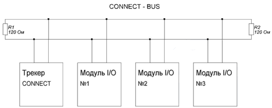
Fig.1 Connect-Bus Topology
For ease of assembly of the Bitrek Connect system, terminating resistors are already installed on the boards of most modules in the system. Each resistor installed on the module board can either be connected to the CAN bus or not. In order to enable the terminating resistor, a jumper (jumper) must be installed in the connector located on the module board and signed as “120E”.
Note: There is no such resistor on the Connect system tracker board.
If there is a need to connect a terminating resistor to a Connect Bus location where a module is installed that does not have a built-in resistor, a special Connect-Bus splitter can be used that has such a terminating resistor.
The Connect-Bus splitter is a connector equipped with four equal Connect-Bus connectors. These splitters are used to build a telematics bus for the Bitrek Connect system, and are used to connect the system modules in parallel to combine them into a single bus. The splitters are of two types: red (with integrated terminating resistor) and blue (without terminating resistor).
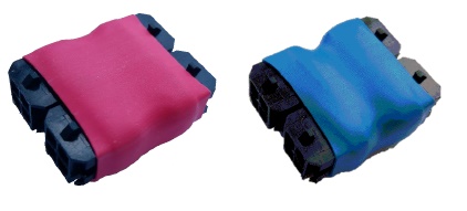
Fig.2. Connect-Bus Splitters exterior view
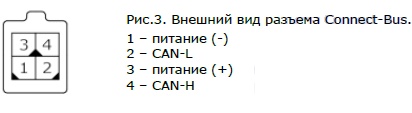
These splitters are equipped with four standard Connect-Bus connectors. The standard Connect-Bus connector is a 4-pin Micro Fit connector, which carries the power supply to the modules and the CAN-H and CAN-L signal lines. The connector pinout is shown in Figure 3.
These are the same standard connectors found in most Connect modules. Modules for external mounting (e.g. module GS01 or BL01) do not have this connector. Instead, the modules have screw terminals on the board for connecting cables. There are also modules that are already equipped with a cable and do not have a standard connector (e.g. module MF01). In this case, you must install the Connect-Bus connector to the cable yourself after installing the equipment and laying the cable. To install the connector, use a special tool - the Micro-Fit pin crimper. When installing, each contact of the connector is crimped separately on the strands, and then the contacts are inserted into the connector.
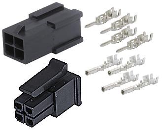
Fig.4. The appearance of the Micro-Fit connectors and contacts
A multicore 0.35 mm2 cable with twisted cores can be used for Connect-Bus installation.
To connect the Connect-Bus elements to each other (e.g. module-module or module- splitter connection), CAN-CAN cables are used - a cable consisting of four separate wires, which are fitted with Connect-Bus connectors on both sides.
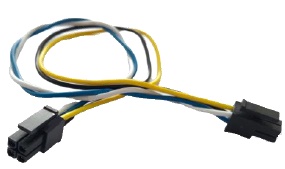
Fig.5. Exterior view of the CAN-CAN cable.
Wires description:
- Yellow - power (+)
- Black - power (-).
- White - CAN-H
- Blue - CAN-L.
The length of the cable is 10-20 cm. It can be used when the connectable parts of the system are close to each other (for example, when installing the equipment under the panel in the cabin of the vehicle, or in a separate box. If there is a need for a longer cable - it is laid separately, then the Micro-Fit connectors are installed on its ends.
Power to the system is supplied by a special power cable. The power cable has one standard Connect-Bus connector and has two wires for powering the system.
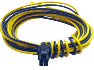
Fig.6. Exterior view of the power cable.
Wires description:
- Yellow - power (+)
- Black - power (-)
The number of Connect modules, their type, and their placement area determine the number and types of connectors needed in the system. For clarity, an example of the configuration is shown below.
Example: to create a Connect-Bus with a BI 810 Connect tracker, EX02 module and BL01 module. The tracker and EX02 module are installed under the front panel of the vehicle, while the BL01 module is installed in the rear of the vehicle. To solve this problem, you need:
- Red splitter - 1 pc
- Power cable - 1 pc
The tracker, the EX02 module and the power cable are connected to the red splitter. There is one free slot left in the splitter - the configurator module is plugged into it to configure the system. The remaining free Connect-Bus connector on the EX02 module is used to connect the BL01 module, which requires a separately purchased cable and Micro-Fit connectors with pins. The connectors will be installed after the cable.
In order to harmonize the Connect-Bus, it is necessary to disable the terminating resistor on the EX02 module board (remove the jumper from the connector on the board), and to connect the terminating resistor in the BL01 module (install the jumper). Thus the Connect-Bus bus will be formed, its longest part will connect the modules installed in the cabin under the panel - on one side, and the BL01 module installed on the rear wall of the vehicle - on the other side. On both sides, the long bus line will be matched with resistors: on the cabin side the resistor is installed in the red splitter, on the rear wall of the vehicle - in the BL01 module.
IMPORTANT! It is not allowed to connect more than two terminating resistors to the Connect-Bus. The resulting resistance between CAN-H and CAN-L is 60 ohms.
Configuring the Bitrek Connect system
General description of Bitrek Connect peripheral modules
The peripheral modules of the Bitrek Connect system are designed as individual devices connected to the Connect-Bus. The modules are divided into two versions: version one (v01) and version two (v02). They are not functionally different, but there is a difference in their design and connection method.
The appearance of the v01 and v02 modules is shown in Figures 7 and 8.
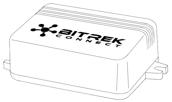
Figure 7. The appearance of module v01.
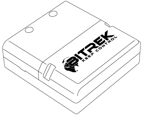
Fig.8. The appearance of the module v02.
The Bitrek Connect v01 modules are equipped with one four-pin Connect-Bus connector and are not equipped with a terminating resistor. To build a Connect-Bus using these modules, you must use splitters anyway.
The Bitrek Connect v02 modules are equipped with two equivalent four-pin Connect-Bus connectors and a terminating resistor on the module board. This resistor is switched on by putting a jumper in the connector on the board, labeled “120E”.
Bitrek Connect configuration sequence. Interaction of the tracker and peripheral modules
Each module of the Bitrek Connect system has its own manual. This manual describes the technical characteristics of the modules, how to put them into operation, pin assignment, and all the necessary technical information.
Each individual module of the system has a list of configurable parameters (each parameter has its own number - parameter ID) and a list of variables that it broadcasts to the Connect-Bus. The variables carry information from the sensors that are connected to the peripheral modules of the Bitrek Connect system. Each module translates these variables to the bus. The system's tracker, which in turn is connected to the bus, can be configured to receive and process these variables. In addition to variables that contain information received from sensors, each module broadcasts system variables to the bus: hardware version of the module, software version, counter of module reboots and counter of module's operating time since reboot.
According to the structure of the system organization, there is a conditional sequence of its configuration, which is divided into 3 stages:
Step 1. Setting up the network addresses of the modules. At this stage, each module is assigned its own unique network address on the Connect-Bus. When configuring the network addresses, it is important to configure the address for each module individually, without grouping them together, in order to avoid possible address conflicts. Useful tip: For convenient configuration and remote maintenance of the system, you can pre-define network address ranges for each module type. For example, the RF02 module can occupy network addresses 2-3, the CN03 module can occupy addresses 7-9, etc.
Step 2. At this point the modules can be connected together via the Connect-Bus. After that the modules are configured to work with external sensors that will be connected to them. At the same step, the modules are configured to communicate with each other, if that is what the configuration calls for.
Step 3. At this stage, the tracker is configured. Setting up the tracker comes down to configuring its main parameters, as well as configuring the internal sensors and CAN-sensors. Each CAN-sensor is configured to work with one variable. All these variables are translated into the Connect-Bus by the modules connected to it and carry the information received from the external sensors. Each CAN sensor of the tracker is configured as a separate I/O item.
The sequence described above is conditional. Monitoring systems based on Bitrek Connect system may include different number of modules, and therefore the configuration sequence may be slightly different.
Configurator module description
All devices connected to the Connect-Bus of the Bitrek Connect system can be configured using the configurator module connected to the bus (Fig. 9). To work with the configurator module a special software - Connect Configurator - is used.
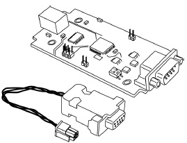
Fig.9. The appearance of the configurator module
Command structure
The module accepts configuration commands generated by the Connect Configurator program and, depending on the recipient, translates them to the Connect-Bus or executes them independently. All modules of the Bitrek Connect system, except the configurator modular, have the ability to set the network address. The address of the modular configurator on the Connect-Bus is FEh and is not configurable. All commands sent to this address are perceived by the module as its own and are executed by it. The configurator module supports the following commands:
getpassport - request the list of passports available on the bus for devices;
clrpassport - erase the list of passports available on the bus;
getver - get the string with the configurator firmware version;
getbusstatus - get the status of the Connect-Bus;
cpureset - to reboot the device.
The format of the answer to the command getpassport:
PASSPORT: index;addr;model;sw
Where:
index - passport index - 0-31 (up to 32 passports);
addr - address of the device on the bus;
model - model of the device;
sw - device firmware version;
Response example:
PASSPORT: 1;1;RL01;0180
The response format to the clrpassport command is <CLRPASSPORT OK>\r
The format of the answer to getver command - <S6 CAN CONFIG VER 1.4>\r
The format of the answer to the command getbusstatus -
<BUS STATUS: STATUS,SPEED;BUSOFFCNT;RXCNT;TXCNT>\r
Where:
STATUS is OFF or OK;
SPEED - current bus speed (0, 125, 250, 500);
BUSOFFCNT - counter of BUS OFF states;
RXCNT - received packets counter;
TXCNT - transmitted packets counter;
There is no response to the cpureset command.
The commands sent to the address, which does not coincide with the address of the configurator module, are translated into the Connect-Bus and executed by other modules, present in the bus.
The configurator module analyzes the data sheets of all peripheral modules on the bus. In case of disconnection of a peripheral module from the bus, the configurator module holds the passport for 5 seconds and then removes the passport of the disconnected device from the memory.
Any peripheral module on the Connect-Bus has its unique (configurable) address. Each configurable parameter has its own number - parameter ID. To request the value of a parameter, getparam command is used. To set the value of a parameter - the command setparam.
An example of a command to request the parameter ID 0216:
getparam 0216;
The structure of the string with the command is as follows:
$addr;string_cmd_0;string_cmd_1;string_cmd_n;
Where:
$ - dollar is the sign of the beginning of the string with the command;
addr - address of the peripheral module on the bus, for which the command is intended. It is always transmitted in HEX-format as 2 ASCII-encoded characters;
string_cmd_0 - string_cmd_n - any text commands supported by the destination (for example: getver; cpureset; getparam xxxx;);
The separator between the commands is always a dot with a comma - ';'.
Multiple commands can be sent in one line. The size of the buffer for commands from the terminal is 1024 characters. Modules on the bus wait for commands addressed to them, then decrypt them and send the answer in the form:
$addr;answer.
Where:
$ - dollar is a sign of the beginning of a line with the answer;
addr is the address of the module on the bus from which the answer is received. It is always transmitted in HEX format as 2 ASCII coded characters;
answer - answer to the command (the structure of the answer depends on the command and is similar to the answer when configuring through the terminal);
To access the configuration of the peripheral module on the bus, you need to send it the terminal access password using the standard TPASS command: xxxx;
Example of sending the command getver and getparam 0241 to the peripheral module with address 0x07. The module has a terminal access password of 11111;
$07;TPASS: 11111;getver;getparam 0241;
$07;TASK COM TERM: PASSWORD OK
$07;Param ID: 0241 Val: 10
$07;<S6 CAN RELAY VER. 1.8>
System modules do not respond to commands if no configuration access password is entered.
Description of messages broadcast to Connect-Bus
Each device performs broadcasting of messages to the Connect-Bus. The identifier of these messages is the PGN (Parameter Group Number) - it is a parameter group number which determines the content of the corresponding message. One PGN can contain several variables. Each individual device on the bus can translate several PGNs to the bus.
Each variable broadcast by a device to the Connect-Bus has a number of parameters:
1. The bit size (CANsize);
The address of the device which translates the variable to the bus (CANAddr);
The PGN is the identifier of the message which contains this variable. It should be noted that one PGN can contain several variables;
4. BitPos - the start bit of the variable;
5. BitTotal (BitNum) - the total bit of the variable;
6. Timeout - the timeout during which the tracker will broadcast the last valid value of this variable. If the timeout is set to 0, then the last valid value will be broadcasted by the tracker all the time.
The Bitrek Connect tracker is configured to receive the desired variables. Receiving variables from the bus, the tracker can operate with these variables as normal I/O items, and depending on the settings of the I/O item, send the received values to server (more information about I/O element settings in Appendix 1).
Connect Configurator software
General description
The Connect Configurator software is designed to generate and send configuration commands to the configurator module. Connect Configurator has a user-friendly interface and is constantly being improved.
With each new peripheral module in the Bitrek Connect system (or firmware upgrade of an existing module), a new library .XML configuration file is released that is needed for Connect Configurator to work correctly with new or upgraded equipment. This file describes all the configurable parameters of the module, as well as the variables that the module can pass to the bus. Before you start, the library .XML configuration file must be copied to the lib folder, which is in the Connect Configurator root folder.
To start working with the equipment, connect the selected modules according to the system topology presented in this manual. At the same time it is necessary to provide reliable power supply for the modules from 12 V or 24 V source.
For the configurator module and Connect Configurator software to work properly, the PC must meet the following requirements:
- Windows XP operating system or newer;
- NET.Framework 4 software platform or higher;
- 1024 MB of RAM or more;
- Free disk space - 50 MB (including logs storage);
- A driver package must be installed for the configurator module.
Appearance of Connect Configurator
Fig. 10 shows the appearance of the configurator program window.
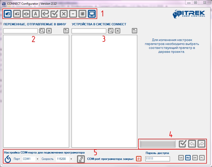
Fig.10. The appearance of the CONNECT Configurator program.
The symbols:
- Toolbar;
- Field for working with variables sent to the Connect-Bus;
- Field for working with devices connected to the Connect-Bus;
- Status bar and sending commands to devices;
- COM port settings to connect the programmer.
Toolbar

Fig.11. CONNECT Configurator toolbar
Symbols:
- Open a library or configuration file;
- Save the current configuration to a file;
- Scanning the network to search for connected modules;
- Switch the configurator between “Address” and “Parameter” modes;
- Set all parameters to default values;
- Select all available parameters/deselect;
- Clear the project;
- Delete the selected device from the project;
- Update the device firmware;
- Terminal window.
Procedure for configuring the Connect system
Address assignment for devices on the Connect-Bus
Before you start working with the devices in the Bitrek Connect system and assembling them into a single system, you need to assign each of the modules a unique Connect-Bus address. To change the address, after connecting one Connect device and the configurator module to Connect-Bus, select the COM port number that corresponds to the configurator module in the Connect Configurator program, set the connection speed to 115200, specify the device access password (11111 by default) and click “connect”. After that, it is necessary to scan the network to identify the currently connected devices. After a successful scan, the program will display an available device in the working field (Fig. 12).
By default, the Connect Configurator software is in “Address” mode, which is indicated by the “A” icon on the program toolbar. The “Address” mode allows you to set or change the addresses of the devices on the Connect-Bus. Addresses are set in decimal notation (DEC).
To set the address, write it in the appropriate field, mark the device to which the command to change the address will be sent, and send the command by pressing the “Send” button. When the operation is complete, the program will display a message about successful address setting.
Fig.12. The list of devices on the Connect-Bus
Configuring the modules of the system
To configure the modules, switch the Connect Configurator program to “Parameter” mode by pressing the appropriate button on the toolbar. The “P” icon indicates that the program is switched to “Parameter” mode.
For each connected device, the program displays a tree-like list of parameters and variables collapsed by default. The name of the list contains the name of the device and its address on the bus (Fig. 13). To configure the module, use the field “Devices in the Connect system”. Expanding the list you can see the parameters available for configuration. The list of all available parameters and their possible values is given in the user's manual for each individual module.
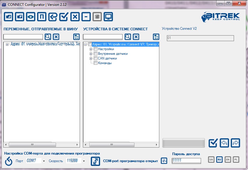
Fig.13. List of parameters and variables
A detailed description of module configuration
Example of module configuration
Below is an example of how to configure the CN module to work with 3 devices via the RS485 bus: 2 fuel level sensors and 1 RFID reader.
Each device connected to the CN module must be preset. Setting is limited to assigning a network address to each device on the RS485 bus. The first fuel level sensor is assigned address 1, the second one address 2, the RFID reader address 9.
Note:
Data exchange between the RFID reader and the CN module is performed according to the RCS SOVA protocol.
Next, you need to configure the CN module itself. Open the tree-like list of module parameters by clicking the “+” symbol. The list will display the “Settings. In the subgroup “RS485 RTC” you need to configure the following parameters: “RTC address” and “RTC polling permission”. Parameters “Interrogation period of the DUT” and “Transmission period of the DUT into the CONNECT-BUS” can be left unchanged.
Since the system will use 2 fuel level sensors, then specify the addresses for each of the sensors on the RS485 bus in the corresponding fields of the configurator (in the example it is the 1st and 2nd addresses) (Fig.14).

Fig.14. Address assignment for fuel level sensors
Mark the parameters to send and send the command (Fig.15).
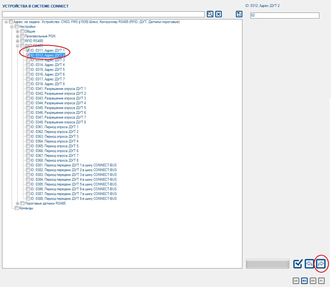
Fig.15. Sending the marked parameters to the module
After that you should enable polling the fuel level dataloggers, mark the parameters to be sent and send the commands.
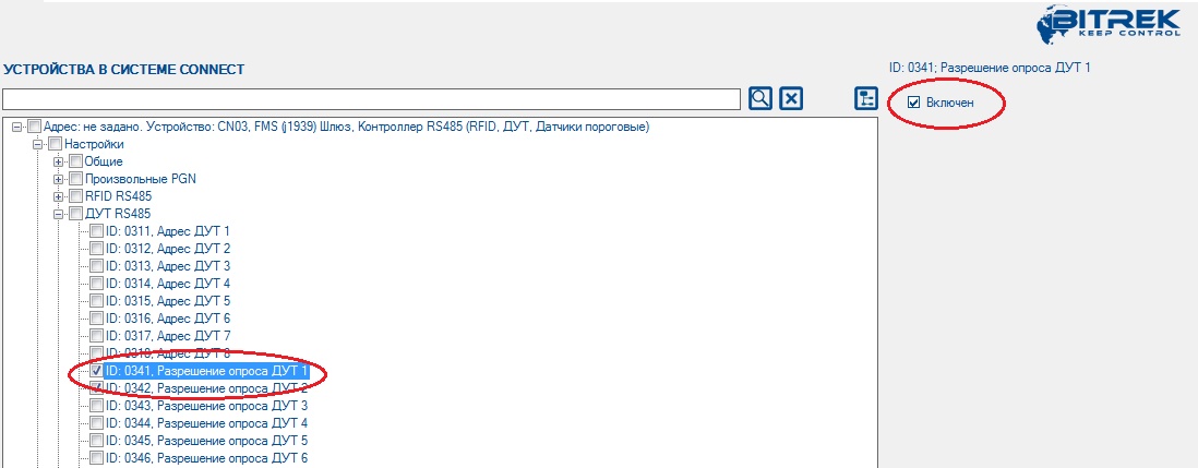
Fig.16. Polling resolution of fuel level sensors
Setting the module for work with the RFID reader is made in the same way: the address of the reader on the RS485 bus is pointed out (in our example it is the 9th address), the reader polling is enabled, the parameters to be sent to the module are marked, and the command (Fig. 17) is sent.
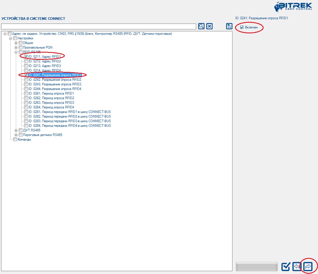
Fig.17. Configuration of the CN module to work with the reader RFID
After that the CN module will poll the network address 1, 2 and 9 on the RS485 bus. The data received from the devices the module will broadcast to the CONNECT-BUS.
Configuration of the tracker
The tracker is configured in the same way. In the list of the device parameters, select the required parameters, enter their values in the appropriate field and send commands to the device. The list of all parameters available for configuration can be found in the configuration and operation manual for the corresponding system module, including the tracker.
The minimum set of parameters required for the tracker to work are GPRS access point, server IP address, server port. Select the required parameters, specify the required values in the field, and click “Send”. You can judge about the successful sending of the parameters by the state of the command line.
Keep in mind that for convenience, you can configure several devices at once and send the parameters selected in the list to several devices on the Connect-Bus at once.
In addition, to view the already recorded parameters you can use the parameter request function. To do this, in the list of available parameters you must mark the parameters you want to view and request them from the devices connected to the bus. Also, when it is necessary to request all available parameters from the Connect devices or to send all parameters to all devices at once - you can use the function of selecting all available parameters at once. To do this, on the toolbar you must click the button “Select all parameters”. To cancel the selection, press the same button again.
Keep in mind that if you select all the parameters at once, their request and sending may take a long time. In this case, the more devices are currently connected to the Connect-Bus, the longer it will take to send/request commands.
Configuring the tracker to receive and process variables
All variables broadcast by modules to the Connect-Bus can be “captured” by the tracker and sent to the server as standard I/O elements (Appendix 1). To configure the tracker to receive and process variables, use the list of variables broadcast to the Connect-Bus and the “CAN-Sensors” settings group in the tracker settings list.
Fig. 18 shows the parameters required for the settings. The CN module selected for the example can broadcast a large number of different variables to the bus. All these variables are divided into corresponding groups. There are corresponding subgroups for fuel level sensors and RFID readers: “RS485 fuel level sensors” and “RFID RS485”.
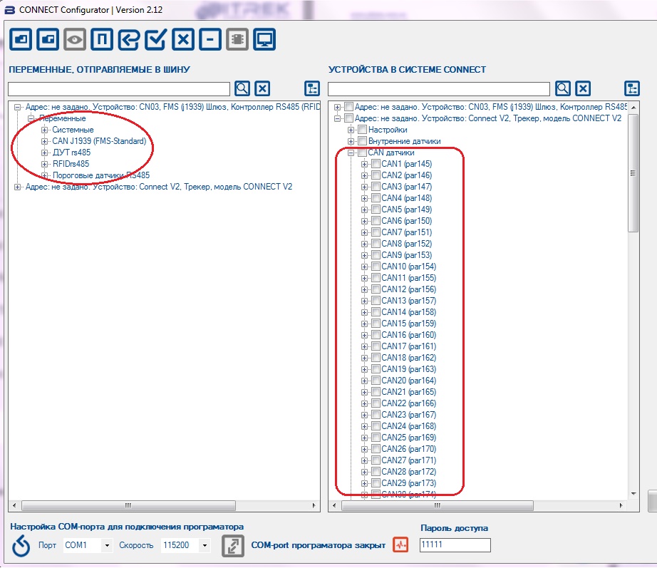
Fig.18. Setting up the variables to be sent to the server
In the RS485 DUT variables subgroup the following variables are displayed which can be sent to the bus: “DUT status”, “DUT temperature”, “DUT fuel”. For the CN module, the maximum number of connected fuel level sensors is 8. That is why all broadcasted variables are set separately for 8 sensors (Fig. 19).
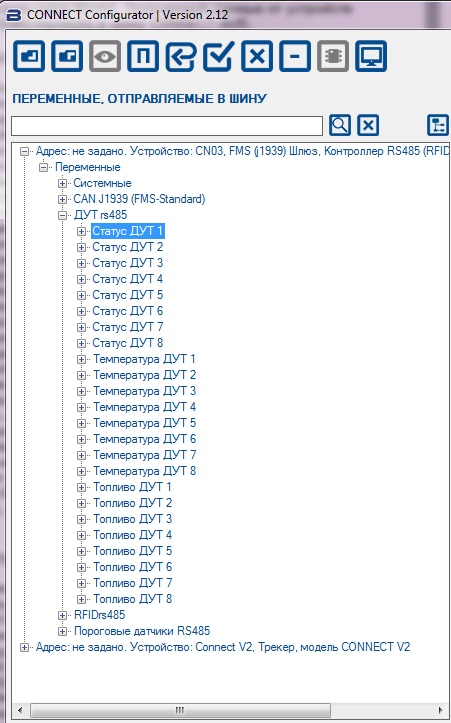
Fig. 19: List of variables for fuel level sensors
Only two variables are available in the “RFID RS485” variable subgroup: RFID Status and RFID Card Number. Up to four RFID readers can be connected to the module in total. Each variable broadcasted to the bus has a number of parameters, which are available for viewing in the variable list.
The tracker allows up to 100 CAN sensors (CAN1 to CAN100) to be transmitted to the server simultaneously. Each such variable has in its turn two subgroups of settings: “I/O” and “CAN” (Fig.20).
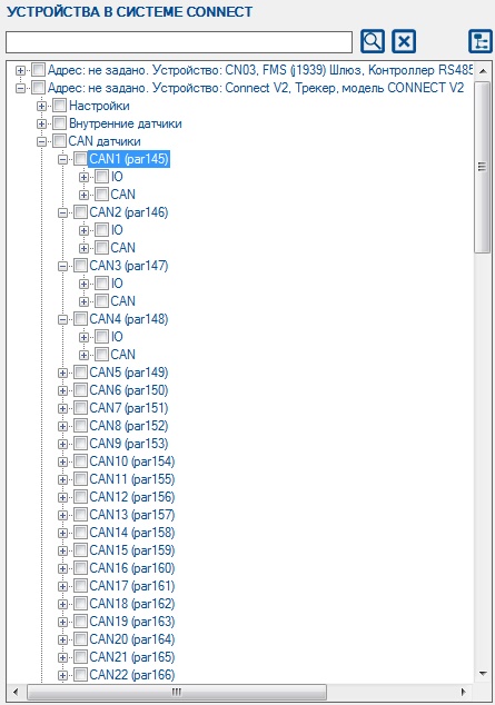
Fig.20. The structure of CAN tracker variables
You can set up the variables to be transmitted from the tracker to the server by dragging them from the left part of the configurator window to one of the “CAN sensors” variables in the right part of the window. right side of the window.
For example: In the “RS485 RTC variables” subgroup of the CN module, select the “Fuel RTC1” variable and, holding down the left mouse button, drag it to the CAN1 variable. This is shown schematically in Fig. 16. After that, all the necessary parameters of the variable “Fuel DUT1” will be automatically written to the CAN-subgroup of the variable CAN1. At that, the name of the variable CAN1 will take a corresponding name.
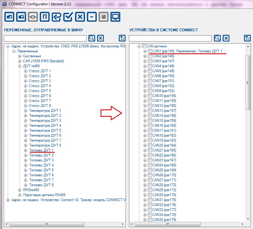
Fig.21. Moving of the variable “Fuel DUT1” to the variable CAN1.
Thus, the CAN-subgroup parameters will be filled in automatically and the next step is to set the I/O subgroup parameters. To do this, expand the list of variable CAN1 tracker and highlight the I/O-subgroup.
Since we are working with the fuel level variable, we will set the I/O element to monitoring mode. To do this, set the following parameters: sensor state - on, priority low, lower limit - 0, upper limit - 0, event type - monitoring, averaging - 10. The settings window is shown on the Fig. 22.

Fig.22. Setting the I/O subgroup parameters
After the parameters have been changed, they must be marked and sent to the devices.
If necessary, all settings can be saved in the configuration file and you will not need to set up the whole project again.
It is important that the network addresses of the devices saved in the configuration file coincide with the addresses of real devices on the Connect-Bus. In case of using the configuration file to set up the system, the following procedure must be followed:
- Assign network addresses to the modules according to the configuration file;
- Connect the modules to the Connect-Bus;
- Search for devices on the bus;
- Make sure that all modules are found and network addresses are assigned correctly;
- Click the “Clear project” button;
- Open the configuration file;
- Select the required settings and send them to the modules.
All the modules of the system are configured as described in this manual.
Appendix 1. Configuring I/O elements
Each tracker sensor is an I/O element and has a group of 6 parameters to configure. For example, to configure the transmission of the power supply voltage level value to the server, the group of parameters ID 0410/0411/0412/0413/0414/0415 is used. These parameters have the following structure:
0410/0411/0412/0413/0414/0415
The first 3 digits (highlighted in bold) are the parameter group number to configure the I/O item.
The last digit (highlighted in monospace) is the parameter number. There are 6 parameters (from 0 to 5) for one I/O element. Possible values of these parameters are shown in Table 1.
Table 1 - List of I/O element parameters
| Parameter number | Description | Possible values |
|---|---|---|
| 0 | I/Off switch of I/O element | 0 - off; 1 - on |
| 1 | Priority of I/O element when sending | 0 - low; 1 - high |
| 2 | Higher boundary | (depends on the type of I/O element) |
| 3 | Lower bound | (depends on the type of I/O element) |
| 4 | Setting the type of event generated | 0 - in range; 1 - out of range; 2 - return to/out of range; 3 - monitoring; 4 - monitoring + in range; 5 - monitoring + out of range; 6 - monitoring + return to/out of range; 7 - event generation upon a set point change in input quantity; 8 - event generation upon a set point change in input quantity + monitoring |
| 5 | Averaging constant | 5 From 0 and up |
Comments to the table 1:
Parameter 0 - Enable/disable transmission of I/O element to the server.
Parameter 1 - Priority: low/high. If you select “Priority: low”, the sensor data will be sent to the server with the next data packet. If you select “Priority: High”, the data will be sent to the server at the first opportunity;
Parameter 2 - Upper bound - setting the upper bound of I/O element;
Parameter 3 - Lower boundary - I/O element lower boundary setting;
Parameter 4 - Setting the type of generated event:
0 - Return to range.
If a certain range of sensor values is set (the range of values is set as follows - the lower limit of the range is written to the corresponding parameter - “Lower limit”, the upper limit - respectively to the parameter “Upper limit”), the event will be generated at the moment when the actual value of the sensor comes within the set range. In other cases the event will not be generated and the information will not be sent to the server. Example: The lower threshold supply voltage is set to 0V, the upper threshold - 10V (10000 mV). When the voltage drops below 10 V the event will be generated (Fig. 18).
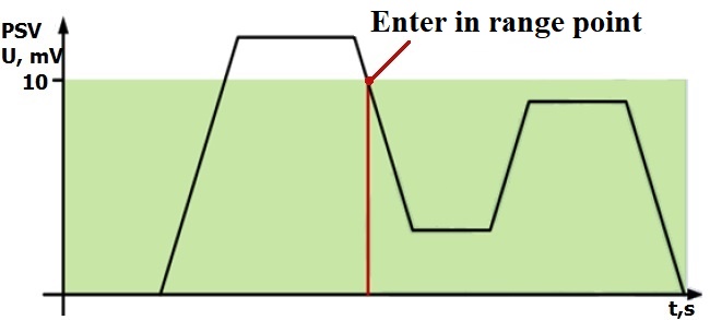
Fig.18. Event generation on return to the range
1 - Return from range.
The event will be generated if the actual value of the sensor exceeds the specified range.
Example: The lower supply voltage threshold is set to 0 V, the upper threshold - 10 V (10000 mV). If the voltage rises above 10 V, an event will be generated (Fig. 19).
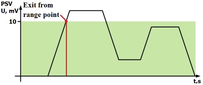
Fig.19. Event generation upon exit from the range
2 - Return/exit to/from range.
The event will be generated each time when the actual value of the sensor crosses the specified range.
Example: The lower supply voltage threshold is set to 5 V (5000 mV), the upper threshold is set to 10 V (10000 mV). When the actual voltage crosses the boundaries of the set range, an event is generated (Fig. 20).
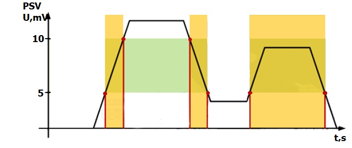
Figure 20. Event generation on return/exit to/from range
3 - Monitoring.
If you select this mode, data will be transmitted continuously, events will not be generated.
4 - Monitoring + range entry.
When a range entry event is generated, the actual sensor value begins to be transmitted to the server in monitoring mode.
5 - Monitoring + range out.
When an out of range event is generated, the actual sensor value starts being sent to the server in the monitoring mode.
6 - Monitoring + return to/out of range.
When one of the events is generated, the actual sensor value starts transmitting to the server.
7 - Changing the input value to a preset value.
When the input value changes by a set value in either direction, an event will be generated. The value of the value is written to the “Upper limit” parameter.
8 - Monitoring + change of input value by set value.
When the event is generated, the actual sensor value starts to be transmitted to the server.
Parameter 5 - Averaging constant is the time during which the I/O element must be in a certain state for the event to be generated. It is measured in milliseconds (X*50 ms, i.e. if you set the value to 10, the constant will be 10*50=500 ms).