BLE trailer equipment identifier
Device Assignment
The BLE Trailer Equipment Identifier is made with Bluetooth Low Energy technology and is designed for the wireless identification of a variety of towed equipment that can be used in conjunction with a tractor, tractor or other machinery.
In various sectors of industry (mainly in the various sectors of industry (mainly in the agricultural sector), there is a need to be able to identify precisely exactly what kind of trailed implement is involved in the work with a particular tractor, tractor, tractor, or other implement. the tractor/tractor currently in use.
The device can also be used as part of friend-or-foe“ system to control the unloading of the combine harvester. In this case this system works in conjunction with the RL module of the Bitrek Connect. This device is used for these tasks. this device is used to solve these tasks.
Technically, the device consists of two functional blocks: BLE radio module and non-contact BLE radio tag. The latter has autonomous power supply that allows using it the last one has an autonomous power supply, which allows using it together with the trailed equipment that has no power source. power supply.
The device works as part of the Bitrek Connect system and is its own functional module. In addition, The device can work separately from the Bitrek Connect system, but with with some limitations.
Package Contents
The BLE Trailer Equipment Identifier comes in the following scope of delivery:
- BLE radio module - 1 piece.
- BLE radio tag - depends on the number of units of trailed equipment (to be specified when ordering).
- Data sheet - 1 pc.
- Warranty card - 1 pc.
Technical characteristics of the device
Technical characteristics of the device are given in table 1. 4
Table 1: Technical specifications of BLE radio module
| No | Parameters | Characteristics |
|---|---|---|
| 1 | Power supply voltage from | 9 to 36 V |
| 2 | Power consumption current | (12V) 17 mA |
| 3 | Output interfaces | CAN, RS485 |
| 4 | Maximum distance between the radio module and the tag | 15 m |
| 5 | Operating temperature range | from -30 °C to +80 °C |
| 6 | Maximum permissible humidity | 80 % ± 15 % |
| 7 | Dimensions (W×D×H) | 92 × 91 × 44 mm |
| 8 | Weight | 146 g |
| 9 | Protection class | IP65 |
Table 2: Technical specifications of BLE radio tags
| No | Parameters | Characteristics |
|---|---|---|
| 1 | Power source | Built-in battery |
| 2 | Battery life | Up to 3 years |
| 3 | Operating temperature range, °C | from -30 °C to +80 °C |
| 4 | Allowable humidity | 80 % ± 15% |
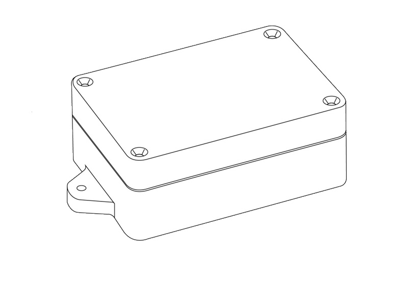
| 5 | dimensions of the radiometer housing (W×D×H) | 108 × 58 × 33 mm |
| 6 | “Weight | 110 g |
| 7 | housing protection class | IP65 |
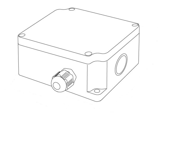
Appearance and design
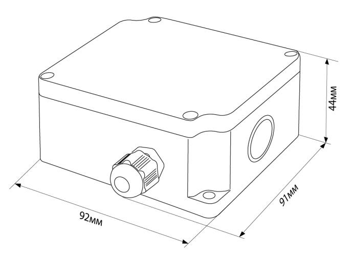
Figure 1. The appearance of the BLE radio module.
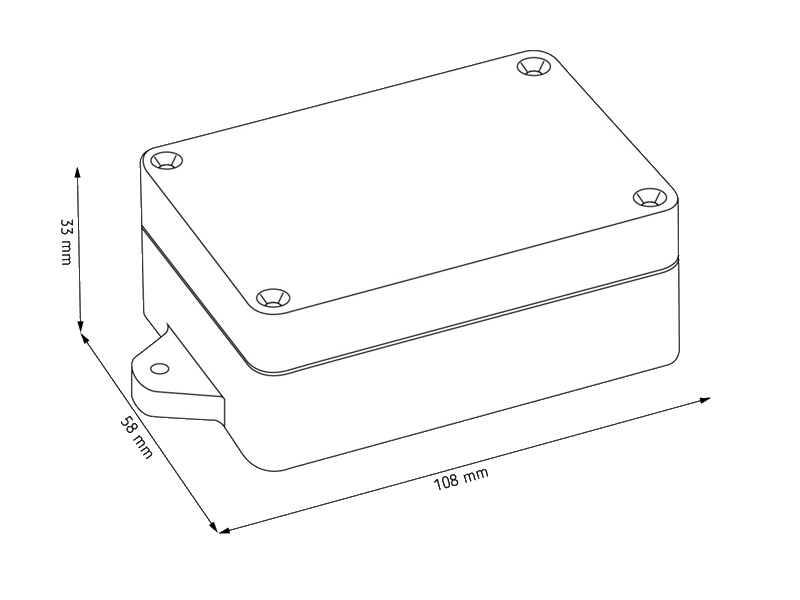
Figure 2: Appearance of the BLE radio module.
Pin assignment
The BLE radio module has a sealed design. The connection cable is led into the module housing through hermetically sealed cable gland and then the cable wires are connected to the card via screw terminal blocks. Beside each terminal block, the pin assignment is indicated on the PCB (see Fig. 3). Next to each terminal block there is a contact designation printed on the PCB (see Figure 3).
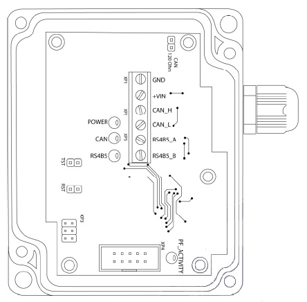
Figure 3: Location of terminal blocks on the board and pin assignment contacts.
The designation of the radio module pins is given in Table 3.
Table 3. pin assignment of BLE radio module
| No. | Name | Assignment |
|---|---|---|
| 1 | GND | common wire (ground) |
| 2 | +VIN | ”+” power supply voltage |
| 3 | CAN_H | CAN bus “CAN_H” signal |
| 4 | CAN_L | CAN bus “CAN_L” signal |
| 5 | RS485_A | RS-485 bus “A” signal |
| 6 | RS485_B | RS-485 bus “B” signal |
The device can transmit data using the interfaces RS485 and CAN (CONNECT-BUS) interfaces, depending on the type of the type of equipment it will be used for. Additionally, a jumper can be installed on the board (jumper) to connect the RS485 and CAN (CONNECT-BUS) interfaces, depending on the type of equipment to be used. Additionally a jumper may be installed on the circuit board, which has a 120 Ohm terminating resistor in parallel with the signal lines of the CONNECT-BUS. The location of the jumper location is shown in Figure 3. By default, the jumper is not jumper is not installed by default.
Principle of operation
The BLE radio tag is installed on the trailed equipment and has an internal power supply. Every 5 seconds, the tag transmits via Bluetooth its unique ID. The BLE radio module installed on the tractor/tractor is always in reception mode. As soon as the radio module receives the tag's Bluetooth ID, it starts broadcasting it to the CONNECT-BUS, and on request it can also transmit it via RS485. When exchanging data between the master device and the BLE radio module via RS485, the SOVA protocol is used. Transmission of the tag ID is transmitted within a specified timeout (available for configuration).
The radio module can simultaneously receive signals of 8 tags. В CONNECT-BUS transmits the tag ID and the level of its signal reception. PGN 18F701 - 18F708 are used. The first byte in the PGN is the tag validity status (used by the RL module to The first byte is the tag validity status (used by the RL module to enable the relay). The second byte is the signal reception level (RSSI, unit dBm). The next 6 bytes - the tag ID.
Please note that when working via RS485 only 5 bytes of the tag ID are transmitted bytes of the ID tag, without the high byte. This is due to limitations of the SOVA protocol.
Depending on the level of signal reception the tag parameters are transmitted to the CONNECT-BUS as follows: In the PGN 18F701 the parameters of the tag that is as close as possible to the to the radio module (has the highest signal level). IN PGN 18F702 8 the parameters of the tag with a weaker signal are transmitted, etc. IN PGN 18F708 transmits the parameters of the tag with the weakest signal.
The main variable to determine the current tag is variable “priority tag ID”. In this variable the ID of the tag that is closest to the reader is passed in this variable. In this case, if to the reader is temporarily close to another tag, then tags will switch only after the timeout specified in parameter ID0210 - “Timeout of holding the priority tag during its change”. The same variable is transmitted via RS485.
The system has the ability to transmit an arbitrary number up to two bytes in size other than the tag ID. To implement this function you need to write arbitrary numbers to the tags, if necessary.
Configuring Label Groups
Labels are customizable. For each label you can set up:
- the group it belongs to;
- an arbitrary number that will be transmitted by the tag along with its own ID.
The tag ID cannot be changed.
For each tag it is possible to set the group to which it belongs. it belongs to. Each tag can belong to only one group, while the reader can simultaneously work with 5 groups of tags.
For example, if at one company the system is used as part of a “friend-or-foe” system to monitor the unloading the combine and in the same company the system is used to identify the towed implements. used to identify trailed implements, there is no need for readers installed at the same location. There's no need for the readers on the harvesters to interact with the tags installed on the trailed units. For this purpose, the working group names of the tags can be different.
The BL reader will only read the tags whose groups which are prescribed in the reader settings. By default, all tags belong to the group BITREK. In the settings of the readers by default also prescribed only one group -. BITREK.
The procedure of setting the tag groups for the readers is similar to setting of any other parameters of the reader. To configure the Connect Configurator program is used. Since the BL reader is a module of the Bitrek Connect system, the principle of configuring this module is the same as the other modules of the system. A description of the principle The configuration principle is described in the document Connect General Manual.
The tags are configured with a special programmer for BLE RFID tags are configured by a special programmer for BLE tags. The following is a step-by-step procedure for configuring the tags.
- Disconnect power element of the tag.
- Connect the box to your PC.
- Launch COM Sender software. Select COM port the programmer is connected to. Press the “Close Port” button.
- Enter the following commands into the program:\
- setparam 0910 GROUP1;
- setparam 0210 1234;\
- saveparam;\
- where,{\
- GROUP1 is the name of the group the tag belongs to;\
- 1234 is an arbitrary number (if necessary)
- Sending the saveparam command is mandatory.
- Connect the programmer to the tag.
- Press “Open port” button.
- Press 'Send' button. After that the commands will be sent to the device.
- Click the “Close Port” button.
- Disconnect the programmer from the tag.
- Connect the battery.
This completes the tag setup.
Installing the device
The device installation should be carried out by qualified technical personnel in compliance with fire safety according to GOST 12.1.004 and electrical safety according to соответствии с ГОСТ 12.1.019.
On the transport at the place of work, the measures of GOST 12.1.1.004 must be respected. requirements of occupational safety rules in accordance with DNAOP 0.00-1.28-97.
The BLE radio module is mounted on the outside of the tractor/tractor in such a way that so that the cover of the device faces towards the trailed side of the trailed implement. The sealed cable gland must be The sealed cable entry must be located underneath. It must be mounted in such a way that it does not interfere with normal tractor/trailer mechanisms. When When connecting the cable, the use of a sealed cable gland is obligatory.
Do not put excessive strain on the connecting cable or Do not overtighten the connecting cable or allow it to be unreliably fastened, pinched, etc.
In places where the cable must be passed through metal partitions, it is recommended that normal cable entry points where cables must be routed through metallic partitions, it is advisable to use the positions of entry. If this is not possible, it is necessary to use rubber gaskets to prevent possible abrasion cable from being pulled through the metal partitions.
The BLE tag should be mounted on the trailed equipment and in a place where it will not interfere with the normal operation of the equipment. The BLE tag is mounted on the trailed equipment and in a location where it will not interfere with the operation of mechanisms of the trailed equipment.
Device configuration
The device has a number of adjustable parameters, the list of which you can find in the table 4. To configure the device use the Configurator module of the Bitrek Connect system, as well as the Connect Configurator software. How to work with the configurator module and the software is described in detail in General guide to organizing and configuring Bitrek Connect. Bitrek Connect“ system is described in detail in the document “General guidelines on organizing and configuring Bitrek Connect system”.
Table 4: Device parameters
| Parameter name | ID when configured | Width | Parameter assignment | Default value |
|---|---|---|---|---|
| Reset timeout | 0101-0108 | 2 bytes | data zero timeout | 10 sec |
| Send Period | 0201-0208 | 2 bytes | CONNECT-BUS send timeout | 10 sec |
| RS485_addr | 0211 | 1 byte | address of the device on the RS485 bus | 9 |
| Status Period | 0209 | 2 bytes | timeout period for sending status of MAC address of the held tag | 100 ms |
| Timeout MAC | 0210 | 2 bytes | Hold timeout of the MAC address of the held tag | 5 sec |
List of variables transferred to CONNECT-BUS
| No | Parameter name | Width | PGN | StartBit | BitTotal | Timeout |
|---|---|---|---|---|---|---|
| 1 | Device model | 4 | 18F713 | 0 | 32 | 10 |
| 2 | Software version | 4 | 18F713 | 32 | 32 | 10 |
| 3 | module operating time | 4 | 18F712 | 0 | 32 | 10 |
| 4 | number of restarts | 4 | 18F712 | 32 | 32 | 10 |
| 5 | ID tag #1 | 8 | 18F701 | 16 | 48 | 15 |
| 6 | ID tag #2 | 8 | 18F702 | 16 | 48 | 15 |
| 7 | ID tag #3 | 8 | 18F703 | 16 | 48 | 15 |
| 8 | ID tag #4 | 8 | 18F704 | 16 | 48 | 15 |
| 9 | ID tag #5 | 8 | 18F705 | 16 | 48 | 15 |
| 10 | ID tag #6 | 8 | 18F706 | 16 | 48 | 15 |
| 11 | ID tag #7 | 8 | 18F707 | 16 | 48 | 15 |
| 12 | ID tag #8 | 8 | 18F708 | 16 | 48 | 15 |
| 13 | Priority Tag ID | 8 | 18F714 | 16 | 48 | 15 |
| 14 | Signal level of tag #1 | 2 | 18F701 | 8 | 8 | 15 |
| 15 | Signal level of tag #2 | 2 | 18F702 | 8 | 8 | 15 |
| 16 | Signal level of tag number 3 | 2 | 18F703 | 8 | 8 | 15 |
| 17 | Label number 4 signal level | 2 | 18F704 | 8 | 8 | 15 |
| 18 | Signal level of tag number 5 | 2 | 18F705 | 8 | 8 | 15 |
| 19 | Signal level of tag number 6 | 2 | 18F706 | 8 | 8 | 15 |
| 20 | Signal level of tag #7 | 2 | 18F707 | 8 | 8 | 15 |
| 21 | Signal level of tag number 8 | 2 | 18F708 | 8 | 8 | 15 |
| 22 | Priority tag signal level | 1 | 18F714 | 8 | 8 | 15 |
| 23 | Arbitrary number of tag #1 | 2 | 18F709 | 8 | 16 | 15 |
| 24 | Arbitrary number of tag #2 | 2 | 18F70A | 8 | 16 | 15 |
| 25 | Arbitrary number of tag number 3 | 2 | 18F70B | 8 | 16 | 15 |
| 26 | Arbitrary number of tag #4 | 2 | 18F70C | 8 | 16 | 15 |
| 27 | Arbitrary number of tag #5 | 2 | 18F70D | 8 | 16 | 15 |
| 28 | Arbitrary number of tag #6 | 2 | 18F70E | 8 | 16 | 15 |
| 29 | Arbitrary number of tag #7 | 2 | 18F70F | 8 | 16 | 15 |
| 30 | Arbitrary number of tag #8 | 2 | 18F710 | 8 | 16 | 15 |
| 31 | Arbitrary number of priority mark | 2 | 18F715 | 8 | 16 | 15 |