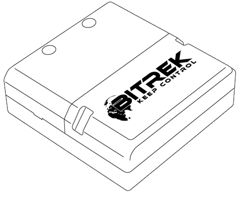
RS02 module of the BITREK CONNECT system
Device assignment
The RS02 module (firmware “GPS”) of the Bitrek Connect system is communication device and is designed to provide communication with any external GPS system for precision farming that equipped with a configurable RS-232 interface.
Package Contents
The RS02 module of the Bitrek Connect system comes in the following complete set:
- RS02 module - 1 pc;
- Data sheet - 1 pc;
- Warranty card - 1 pc;
- Packing box - 1 pc;
- Micro Fit 4-pin cable - 1 pc;
- Micro Fit 6-pin cable - 1pc;
- Rubber gasket - 3pc.
Device specifications
Technical characteristics of the device are presented in Table 1.
Table 1: Technical specifications of the device
| № | Parameters | Characteristics |
|---|---|---|
| 1 | Power supply voltage | from 9 V to 36 V |
| 2 | Consumption current | 20 mA |
| 3 | connection interface | RS-232 |
| 4 | Operating temperature range | -30°C to +80°C |
| 5 | Allowable humidity | 80 ± 15% |
| 6 | Dimensions | (W × D × H) 78 × 83 × 30 mm |
| 7 | Weight | 130 g |
| 8 | housing protection class | IP44 |
Appearance and dimensions of the device
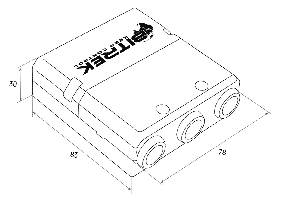
Fig.1. Appearance and dimensions
Pin assignment
The CN03 module is equipped with three Micro-Fit connectors (Fig. 2).
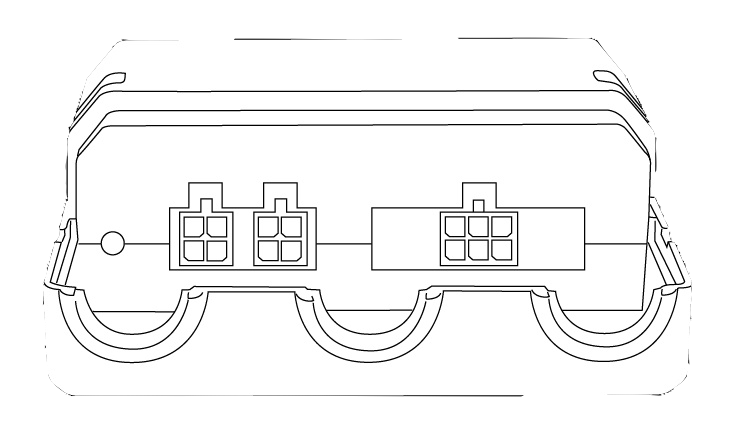
Fig.2. The appearance of the connectors
The four-pin connectors (Fig. 3) are Connect-Bus connectors, which have the power outputs of the module and the outputs signal lines of the bus.
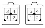
Fig.3. Connect-Bus connectors #1 and #2
The pinout of the Connect-Bus connectors is shown in Table 2.
Table 2 The pin-out of the Connect-Bus connectors No.1 and No.2
| № | Pin name | Signal type | Pin assignment |
|---|---|---|---|
| 1 | GND | Power supply | General lead (ground) |
| 2 | CAN L | Input/output | Signal “CAN_L” of the CAN bus |
| 3 | + Vin | Power supply | “+” On-board power supply (nominal voltage 12 V or 24 V) |
| 4 | CAN H | input/output | signal “CAN_H” on the CAN bus |
The six-pin connector (Fig.4) is the connector for the “CAN-Log” connector. It has power outputs and signal lines of the RS-232.
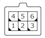
Fig.4. Connector for connecting “CAN-Log”
The connector pinout for connecting “CAN-Log” is presented in of the “CAN-Log” connector is presented in Table 3.
Table 3: Connector pinout for connecting “CAN-Log”.
| № | Contact name | Signal type | Pin assignment |
|---|---|---|---|
| 1 | RX D | Input/Output | RS-232 interface RX signal |
| 2 | + Vin | Power | “+” output of onboard power supply (for power supply to external devices) |
| 3 | GND | power supply | common wire (ground) |
| 4 | TX D | input/output | RS-232 TX interface signal |
| 5 | + Vin | power supply | output “+” on-board power supply (for power supply to external devices) |
| 6 | GND | power supply | common wire (ground) |
Description of indications
On the front panel of the module on the connector side there are two
LEDs that indicate the current status of the device.
Red LED - Illuminates when the Connect-Bus
Connect-Bus connection is active;
Green LED - blinks if there is RS-232 communication
GPS Antenna Setup
The RS02 module of Bitrek Connect uses the RS-232 interface, the module receives data from the precision agriculture antenna. The module transmits the received data to the Connect-Bus.
The module is capable of receiving data from various antennas of Precision farming and parallel driving systems. The prerequisite is an unoccupied RS-232 interface that can be The main condition is that there is an unoccupied RS-232 interface that can be configured by the user.
Configuring the RS-232 interface of an external GPS system
configuration comes down to:
- setting the protocol type - NMEA
- setting the frequency of data transmission - from 1 to 10 Hz
- NMEA strings transmitted: GGA, VTG,
RMC\\.
- the RS232 interface speed must match
one of the following options: 600, 1200, 2400, 4800, 9600, 14400,
19200, 28800, 38400, 56000, 57600, 115200.
In the RS02 settings, you must specify the speed that speed set on the external GPS system.
Connecting GPS antenna to RS02 module
The GPS antenna is connected to the RS02 module via RS-232 interface: The RX signal of the antenna is connected to the TX of the RS02 module, and vice versa (see Table 5.)
Table 5. Antenna connection to RS-02 module
| SEO CAN-LOG | Connect | RS02 module | |
|---|---|---|---|
| Pin name | Pin number | Pin name | |
| RS 232 Rx | ⇔ | 4 | TX D |
| RS 232 Tx | ⇔ | 1 | RX D |
| GND | ⇔ | 3 or 6 | GND |
| + Vin | ⇔ | 5 or 2 | + Vin |
Please note that connecting the antenna power supply to the RS-02 module outputs is for information purposes only. It is not obligatory. Antenna power supply must be constant and not disappear during operation of the vehicle. vehicle operation. Consequently, connection is allowed at any convenient point.
RS02 module configuration
The RS02 module has a number of configurable parameters of which are listed in Appendix 1. To configure the module module is configured using the Bitrek Connect configurator module, as well as Connect Configurator software. How to work with the configurator module and The software is described in detail in the document “General guide to organizing and configuring Bitrek Connect. General guide to organizing and configuring Bitrek Connect system” document.
Configuration of the module boils down to setting the correct speed of data exchange via RS-232 interface. The speed can be set based on the following options: 600, 1200, 2400, 4800, 9600, 14400, 19200, 28800, 38400, 56000, 57600, 115200. The selected speed of the external GPS system must correspond to the one selected in module settings.
Next you need to configure the Connect tracker, namely: you must select the RS02 module as the source for GPS coordinates, because the default setting is the tracker's built-in antenna by default.
To do this, in the Connect tracker, go to Settings ⇒ Service. Service and in the parameter 0201 specify the address of the RS02 module on the Connect-Bus (see Fig. 5).
Figure 5. Selecting the source of coordinate determination
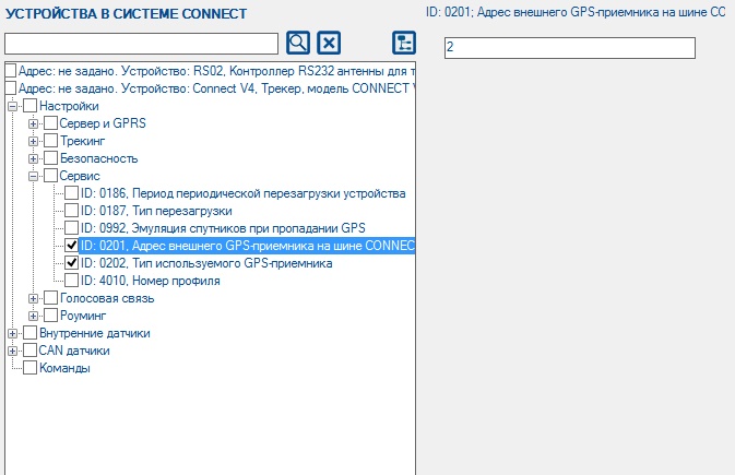
Next, set parameter 0202 “Type of GPS receiver used Receiver Type” to the value “Both antennas, priority - external”. When This setting will use GPS coordinates as the priority. coordinates from the precision farming antenna will be used as the priority, but in case of loss of GPS signal from precision farming antenna disappears, the tracker will switch to its own.
Appendix 1 . Device parameters
| No | Parameter name | ID when configured | Parameter digit | Parameter assignment | Default value |
|---|---|---|---|---|---|
| 1 | CANSlaveAddr | 0200 | 1 byte | device address on Connect - Bus | 4 |
| 2 | DevicePIN | 0400 | 2 bytes | Device access password | 11111 |
| 3 | BaudRate | 0403 | 2 bytes | RS-232 data rate | 9600 |
| 4 | MinGPSSpeed | 0918 | 2 bytes | minimum GPS speed | 5 |
| 5 | GPSErrSatNum | 0992 | 1 byte | number of satellites when GPS signal is lost | 0 |
| 6 | MaxHDOP | 0998 | 2 bytes | Maximum HDOP | 500 |
Addendum 2. List of variables translated to Connect-Bus
| № | Parameter name | Width | PGN | Start Bit | Bit Total | Timeout |
|---|---|---|---|---|---|---|
| 1 | Device model | 4 | 18F713 | 0 | 32 | 10 |
| 2 | Software version | 4 | 18F713 | 32 | 32 | 10 |
| 3 | module operating time | 4 | 18F712 | 0 | 32 | 10 |
| 4 | number of module starts | 4 | 18F712 | 32 | 32 | 10 |
| 5 | Latitude | 4 | 18FEF3 | 0 | 32 | 5 |
| 6 | Longitude | 4 | 18FEF3 | 32 | 32 | 5 |
| 7 | Azimuth | 2 | 18FEE8 | 0 | 16 | 5 |
| 8 | Speed | 2 | 18FEE8 | 16 | 16 | 5 |
| 9 | Pitch | 2 | 18FEE8 | 32 | 16 | 5 |
| 10 | Height | 2 | 18FEE8 | 48 | 16 | 5 |