RS02 module of the BITREK CONNECT system
Device assignment
The RS02 module (firmware “CAN-Log”) of the Bitrek Connect system is a communication device and is designed for providing communication with the universal programmable controller CAN-Bus “CAN-Log” P145/U245.
Package Contents
The RS02 module of the Bitrek Connect system is delivered in the following configuration:
- RS02 module - 1 pc;
- Data sheet - 1 pc;
- Warranty card - 1 pc;
- Packing box - 1 pc;
- Micro Fit 4-pin cable - 1 pc;
- Micro Fit 6-pin cable - 1pc;
- Rubber gasket - 3pc.
Device specifications
Technical characteristics of the device are presented in Table 1.
Table 1: Technical specifications of the device
| № | Parameters | Characteristics |
|---|---|---|
| 1 | Power supply voltage | from 9 V to 36 V |
| 2 | Consumption current | 20 mA |
| 3 | connection interface | CAN-Log RS-232 |
| 4 | Operating temperature range | -30°C to +80°C |
| 5 | Allowable humidity | 80 ± 15% |
| 6 | Dimensions | (W × D × H) 78 × 83 × 30 mm |
| 7 | Weight | 130 g |
| 8 | housing protection class | IP44 |
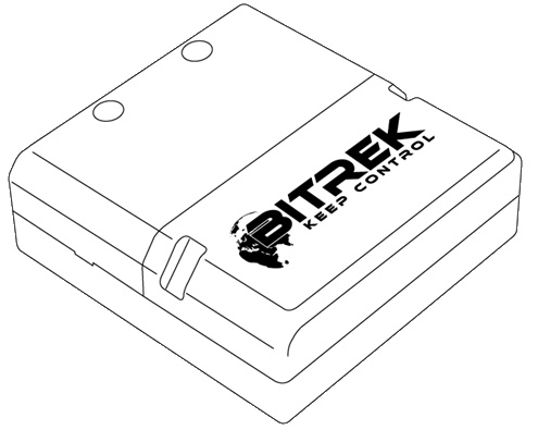
Appearance and dimensions of the device
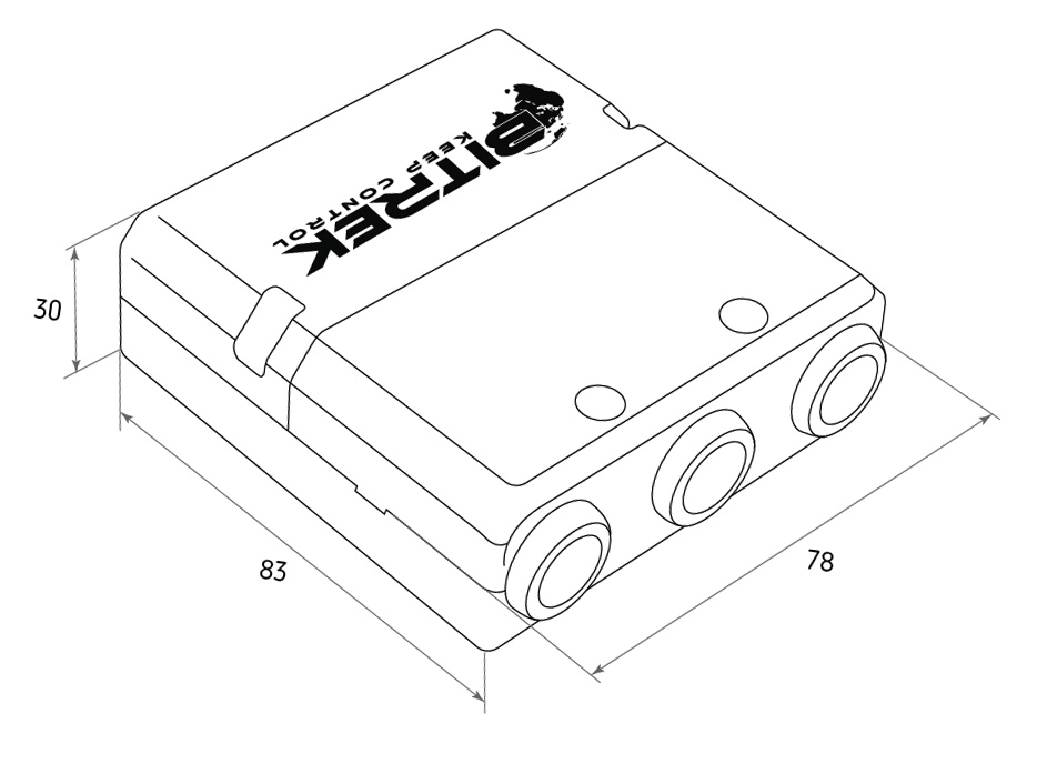
Fig.1. Appearance and dimensions
Pin assignment
The CN03 module is equipped with three Micro-Fit connectors (Fig. 2).
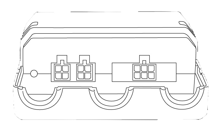
Fig.2. The appearance of the connectors
The four-pin connectors (Fig. 3) are Connect-Bus connectors, which have the power outputs of the module and the outputs signal lines of the bus.
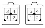
Fig.3. Connect-Bus connectors #1 and #2
The pinout of the Connect-Bus connectors is shown in Table 2.
Table 2 The pin-out of the Connect-Bus connectors No.1 and No.2
| № | Pin name | Signal type | Pin assignment |
|---|---|---|---|
| 1 | GND | Power supply | General lead (ground) |
| 2 | CAN L | Input/output | Signal “CAN_L” of the CAN bus |
| 3 | + Vin | Power supply | “+” On-board power supply (nominal voltage 12 V or 24 V) |
| 4 | CAN H | input/output | signal “CAN_H” on the CAN bus |
The six-pin connector (Fig.4) is the connector for the “CAN-Log” connector. It has power outputs and signal lines of the RS-232.

Fig.4. Connector for connecting “CAN-Log”
The connector pinout for connecting “CAN-Log” is presented in of the “CAN-Log” connector is presented in Table 3.
Table 3: Connector pinout for connecting “CAN-Log”.
| № | Contact name | Signal type | Pin assignment |
|---|---|---|---|
| 1 | RX D | Input/Output | RS-232 interface RX signal |
| 2 | + Vin | Power | “+” output of onboard power supply (for power supply to external devices) |
| 3 | GND | power supply | common wire (ground) |
| 4 | TX D | input/output | RS-232 TX interface signal |
| 5 | + Vin | power supply | output “+” on-board power supply (for power supply to external devices) |
| 6 | GND | power supply | common wire (ground) |
Description of indications
On the front panel of the module on the connector side there are two LEDs on the connector side of the front panel indicate the current status of the device. Red LED - Illuminates when the connection to the Connect-Bus connection is active;\\* Green LED - blinks when RS-232 communication is active.
Module Algorithm
The RS02 module of the Bitrek Connect system communicates via the RS-232 interface the module communicates with the “CAN-Log” device. The module receives data from the device and transmits them to the Connect-Bus.
A total of 29 predefined PGNs are sent to the bus. The list of all variables broadcast to the bus is presented in the Addendum 2.
Some of the variables that are translated to the bus can contain zeros. This situation is possible if:
- The set interrogation period of the sensor is longer than the sending period of the variable containing the value of that sensor;
- The “CAN-Log” device does not send information on the current sensor.
Configuring the RS02 module
The RS02 module has a number of configurable parameters of which are listed in Appendix 1. To configure the module The Bitrek Connect configurator module is used, as well as Connect Configurator software. How to work with the configurator module and The software is described in detail in the document “General Guide to Organizing and Configuring the Bitrek Connect System. The general guide to organizing and configuring Bitrek Connect system”.
The RS02 module is compatible with the “CAN-Log” modules of both older versions (P145) and new (U245) modules. The selection of the “CAN-Log” version is done by the parameter ID 0405.
The RS02 module has the possibility to set the working of the “CAN-Log” module. For this purpose in the module parameter ID 0404 it is necessary to enter the desired number of the “CAN-Log” program. At If the value 0 is entered in this parameter, the program number program number will not be changed.
It should be borne in mind, that the setting of the program number will take place only after restarting the module.
It is possible to check the communication between the “CAN-Log” module and the RS02 module. For this purpose the test program CANLog must be installed. In this mode CAN-Log simulates the connection to the external CAN bus of the vehicle and transmits a number of test parameters. These parameters are read out and transmitted to the Connect-Bus. Consequently, it is possible to set these parameters for server by means of a Connect tester. The parameters that can be used as control parameters can be used as parameters coolant temperature and engine speed.
The test program number for the “CAN-Log” version P145 is 188. For version U245 the test program number is 11188.
The basic setting of the module is reduced to setting only two the version of the “CAN-Log” protocol and the number of the “CANLog ”. After these parameters are set correctly, the RS02 module will start transmitting to the bus a number of parameters received from the “CAN-Log”.
Connecting the "CAN-Log" to the RS02 module
The RS-232 interface connection of the “CAN-Log” module and the RS02 module is connected crosswise: the RX signal of the “CAN-Log” module is connected to the TX signal of the RS02 module (see Table 5.)
Table 5. Connection diagram of the “CAN-Log” module
| SEO CAN-LOG | Connect | RS02 module | |
|---|---|---|---|
| Pin name | Pin number | Pin name | |
| RS 232 Rx | ⇔ | 4 | TX D |
| RS 232 Tx | ⇔ | 1 | RX D |
| GND | ⇔ | 3 or 6 | GND |
| + Vin | ⇔ | 5 or 2 | + Vin |
Appendix 1 . Device parameters
| № | Parameter name | ID when configured | Parameter digit | Parameter assignment | Default value |
|---|---|---|---|---|---|
| 1 | CANSlaveAddr | 0200 | 1 byte | The device address on the Connect-Bus | 4 |
| 2 | CANLogPrgNum | 0404 | 2 bytes | CAN Log program number | 188 |
| 3 | SturtupNum | 0405 | 4 bytes | CAN Log protocol version | 0 |
| 4 | BusSendPeriod | 0700 | 1 byte | 1 byte CAN Log data sending period to Connect-Bus | 1100 |
| 5 | CANLogPollingPeriod | 0701 | 1 byte | CAN Log polling period, in seconds | 5 |
| 6 | DevicePIN | 0910 | 1 byte | Device access password | 11111 |
Addendum 2. List of variables broadcasted to the Connect-Bus
| № | Parameter name | Width | PGN | Start Bit | Bit Total | Timeout | Discreteness |
|---|---|---|---|---|---|---|---|
| 1 | Device model | 4 | 18F713 | 0 | 32 | 10 | - |
| 2 | Software version | 4 | 18F713 | 32 | 32 | 10 | - |
| 3 | module operating time | 4 | 18F712 | 0 | 32 | 10 | 1 sec |
| 4 | number of starts of the module | 4 | 18F712 | 32 | 32 | 10 | pcs |
| 5 | engine runtime | 4 | 18F715 | 32 | 32 | 5 | 1 sec |
| 6 | vehicle mileage | 4 | 18F716 | 0 | 32 | 5 | 0.005 km |
| 7 | Fuel consumption | 4 | 18F716 | 32 | 32 | 5 | 0.05 l |
| 8 | Fuel level in the tank (liter or %) | 2 | 18F717 | 0 | 16 | 5 | 0.1 l/0.1 % |
| 9 | Engine speed | 2 | 18F717 | 16 | 16 | 5 | 0,25 rpm |
| 10 | Motor temperature | 1 | 18F717 | 32 | 8 | 5 | -60 °C |
| 11 | vehicle speed | 1 | 18F717 | 40 | 8 | 5 | 1/256 km/h or 1 km/h |
| 12 | axle load #1 | 2 | 18F717 | 48 | 16 | 5 | 0.5 kg |
| 13 | axle load #2 | 2 | 18F718 | 0 | 16 | 5 | 0.5 kg |
| 14 | axle load #3 | 2 | 18F718 | 16 | 16 | 5 | 0.5 kg |
| 15 | axle load #4 | 2 | 18F718 | 32 | 16 | 5 | 0.5 kg |
| 16 | axle load #5 | 2 | 18F718 | 48 | 16 | 5 | 0.5 kg |
| 17 | Harvesting time | 4 | 18F71A | 0 | 32 | 5 | 1 min |
| 18 | Harvested area | 4 | 18F71A | 32 | 32 | 5 | 1/10000 ha |
| 19 | Capacity | 2 | 18F71B | 0 | 16 | 5 | 1/100000 ga/h |
| 20 | harvested yield | 4 | 18F7B | 16 | 16 | 5 | 1 kg |
| 21 | grain moisture | 2 | 18F71B | 48 | 16 | 5 | 0,1% |
| 22 | AdBLUE liquid level | 2 | 18F71C | 0 | 16 | 5 | 0.1% |
| 23 | threshing drum speed | 2 | 18F71C | 16 | 16 | 5 | 1 rpm |
| 24 | Outlet drum clearance | 2 | 18F71C | 32 | 16 | 5 | 1 mm |
| 25 | Accelerator pedal position | 1 | 18F71C | 48 | 8 | 5 | 0.4% |
| 26 | engine load | 1 | 18F71C | 56 | 8 | 5 | 1 % |
| 27 | mileage to next service | 2 | 18F71D | 16 | 16 | 5 | 1 km |
| 28 | excess mileage | 2 | 18F71D | 32 | 16 | 5 | 1 km |
| 29 | mileage after service | 2 | 18F71D | 48 | 16 | 5 | 1 km |