RF02 module of the BITREK CONNECT system

Device Purpose
The RF02 module of the Bitrek Connect system is designed to work with RFID-readers of electronic cards working via RS-485 interface and using for information transfer protocol “RCS SOVA”. The module has a non-volatile memory, in which which can store the numbers of valid cards. The received number card number and validity status is translated into the Connect-Bus and can be used by other modules of the Bitrek Connect system.
Package Contents
The RF02 module of Bitrek Connect is delivered in the following configuration:
- RF02 module - 1 pc;
- Data sheet - 1 pc;
- Warranty card - 1 pc;
- Packing box - 1 pc.
- MicroFit 4-pin cable - 1 pc.
- MicroFit 6-pin cable - 1pc.
- Rubber seal - 3 pcs.
Technical characteristics of the device
Technical characteristics of the device are presented in Table 1.
Table 1: Technical specifications of the device
| № | Parameters | Characteristics |
|---|---|---|
| 1 | Power supply voltage | from 9 V to 36 V |
| 2 | Power consumption | (12V) 20mA |
| 3 | Interface for connecting RFID readers | RS-485 |
| 4 | Maximum number of RFID readers | 4 |
| 5 | RFID reader communication protocol | RCS SOVA |
| 6 | Maximum number of cards stored in memory | 4000 |
| 7 | Operating temperature range | from -30 °C to +80 °C |
| 8 | Allowable humidity | 80% ± 15% |
| 9 | Dimensions (W × D × H) | 78 × 83 × 30 mm |
| 10 | Weight | 125 gr. |
| 11 | housing protection class | IP44 |
Appearance and dimensions of the device
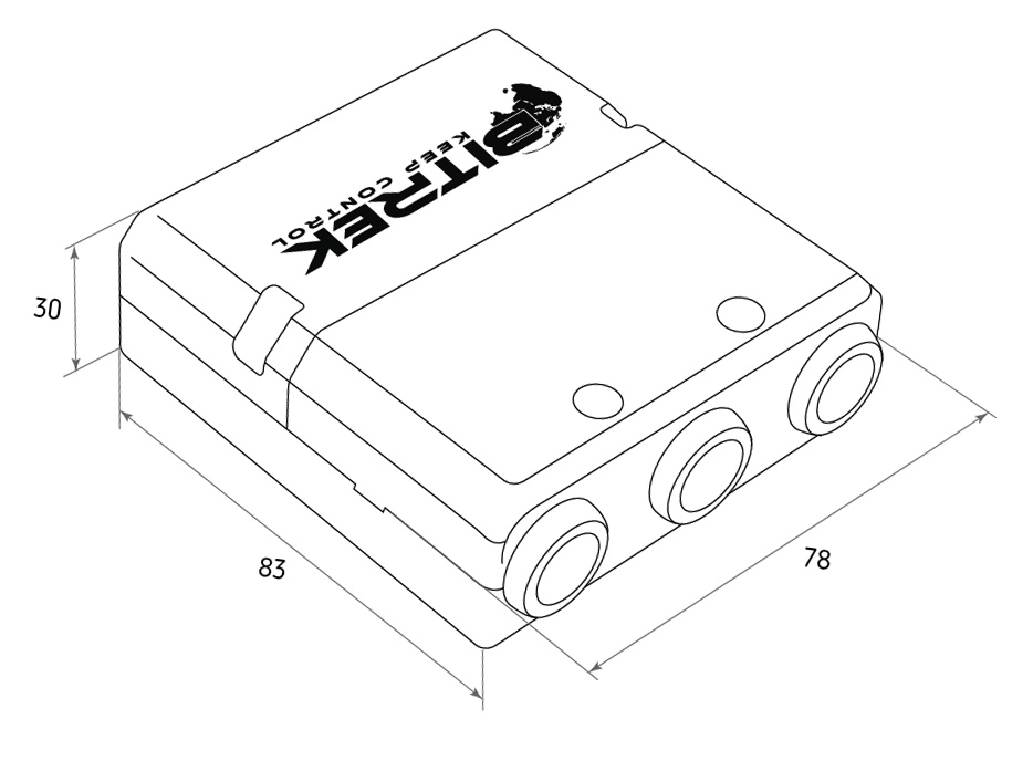
Fig.1. Appearance and dimensions
Pin assignment
The RF02 module has three Micro-Fit connectors (Fig. 2).

Fig.2. Connectors Appearance The four-pin connectors (Fig. 3) are Connect-Bus connectors, which have power supply pins of the module and pins signal lines of the bus.
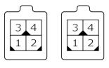
Fig.3. Connect-Bus connectors #1 and #2
The pinout of the Connect-Bus connectors is shown in Table 2.
Table 2 The pin-out of the Connect-Bus connectors No.1 and No.2
| № | Contact name | Signal type | Pin assignment |
|---|---|---|---|
| 1 | GND | Power supply | General lead (ground) |
| 2 | CAN L | Input/output | Signal “CAN_L” of the CAN bus |
| 3 | + Vin | Power supply | “+” On-board power supply (rated voltage 12 V or 24 V) |
| 4 | CAN H | I/O signal | “CAN_H” on the CAN bus |
The six-pin connector (Fig.4) is the connector for connecting RFID readers. It has power outputs of the readers and RS-485 signal lines.
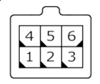
Fig.4. Connector for connecting external devices
The connector pinout for the connection of the RFID-readers is presented in table 3.
Table 3. External devices connector pinout
| № | Contact name | Type of signal | Purpose of contact |
|---|---|---|---|
| 1 | GND | power supply | common ground |
| 2 | CAN H | input/output | CAN_H signal |
| 3 | RS485 A | input/output | RS485 “A” signal |
| 4 | + Vin | Power output | “+” on-board power supply (to power external devices) |
| 5 | CAN L | input/output | “CAN_L” signal on the CAN bus |
| 6 | RS485 B | input/output | RS485 “B” signal |
Description of indications
On the front panel of the module on the connector side there is LED on the connector side of the module, which shows the current status of the device. This LED is lit steadily if the connection to the Connect-Bus connection is successful.
Description of module operation
The RF02 module of the Bitrek Connect system works with RFID-card readers working on the protocol RCS SOVA. To one module can be connected to up to four readers via RS-485 interface.
When receiving the number of RFID card from one of the readers, module performs a search of the received number in the memory. If the number card is found in memory, the module transmits it to the Connect-Bus Connect-Bus. In this case the validity status of the card is broadcasted, which indicates that the card is valid. If the code of the received card is not found in the memory - the module broadcasts into the bus number of the received card and its status - “alien card”.
The card status parameter can be sent by the Bitrek Connect as a separate sensor, or used by other modules of Bitrek Connect system. For example, the status the validity status of the received card can be used by the RL02 module to control the load connected to it.
The status and card number variables are broadcast in a single PGN. Each connected RFID reader has its own PGN. to each connected RFID reader. A list of all broadcast variables is presented in Appendix 2.
Note that up to 4 RFID readers can be connected to one RF02 module Note that up to 4 RFID readers can be connected to one RF02 module. In this case, the storage base card numbers storage in the module is common for all connected readers.
RF02 module configuration
The RF02 module has a number of configurable parameters of which are shown in Appendix 1. To configure the RF02 module The Bitrek Connect configurator module is used, as well as the Connect Configurator software. How to use the configurator module and Software are described in detail in the “Guidelines for organizing and configuring Bitrek Connect”.
The basic parameters that need to be configured for the of the module are as follows:
1. Network address of the RF02 module on the Bitrek Connect bus. The address must be unique to prevent collisions on the bus.
2. Permission to interrogate the connected RFID reader must be be enabled.
3. The network address of the connected reader on the RS-485 bus 3. The network address of the connected reader on the RS-485 bus must coincide with the address of the reader.
During operation, one of the two modes of operation should be selected: with with a data length of 5 bytes or 4 bytes. This setting determined by the value of the parameter 0201. The default value parameter is set to 0, which corresponds to the mode with 5 bytes cards with a length of 5 bytes.
In case of operation with a full card key (5 bytes) the device transmits the full card number from the Connect-Bus.
In case of working in 4 bytes mode, the device will The device will broadcast the card number excluding the first one. The resulting number in In most cases the number received in this mode will correspond to the number printed on the RFID card.
The module allows you to store in memory up to 4096 card numbers. To work with the module memory the commands given in commands from Table 4.
Table 4. List of commands for working with the RF02 module
| № | Command | Description |
|---|---|---|
| 1 | setparam #### | set parameter value by ID |
| 2 | getparam #### | retrieve parameter value by its ID |
| 3 | saveparam | save parameters to FLASH |
| 4 | addekey | add electronic key |
| 5 | getekey | get key by index |
| 6 | matchekey | search for a key in memory with an index |
| 7 | formatekey | delete all numbers of electronic keys from memory |
| 8 | clearekey | delete all electronic key numbers from memory |
| 9 | getver | query the software version of the device |
Explanation of Table 5:
Set parameter value by its ID value/request
To set the parameter value by ID value/request the parameter value by ID value.
Standard commands for reading and writing parameters device. A list of all configurable parameters is given in Appendix 1.
Save parameters to FLASH.
After each change of settings, the module must send the command: saveparam.
After receiving this command, the module sends a response in the form: “PARAM SAVED” and saves the changed parameters in the FLASH memory.
Adding electronic key.
Example command:
addekey XXXXXXXXXXXX;
where:
addekey - command;
XXXXXXXXXXXX -ID of the electronic key, 10 characters strictly.
In response, the result of the save with the result code is sent.
The following answers are possible:
“addekey: OK,XXXX” - key was successfully saved to the cell with the index
XXXX;
“addekey: MATCH,XXXX” - key match was found in the cell
with the index XXXX;
“addekey: ERR,0” - storage failure due to memory overflow
“addekey: ERR,0” - storage failure due to memory overflow.
Getting electronic key by index.
This command is used to read from the device memory the ID of the electronic key by its index. An example of this command is getekey XXXX;
where:
getekey - command;
getekey is the key index.
In response, the result is sent with a key or a result code.
The possible responses are as follows:
“getekey: XXXX,YYYYYYYYY” - ASCII coded key
key;
“getekey: XXXX,EMPTY” - the specified cell is empty;
“getekey: XXXXX,UNFORMATED” - the formatting of this key has failed.
key has failed to be formatted.
Search for a key in memory and generate an index.
This command searches the key in the memory of the device.
When the key matches, the index of the cell with the stored
of the stored key.
Example:
matchekey XXXXXXXXXX;
where:
matchekey - command;
XXXXXXXXXXXX - ASCII coded key.
The answer sends the result of the search with the result code
of the result.
The possible answers are as follows:
“matchekey: OK,YYYY>” - match found in the cell with the index
YYYY;
“matchekey: ERR>” - no match found.
Deletes all electronic key numbers from the memory.
This command erases all electronic key numbers from the memory.
of electronic keys in the memory.
Example command:
formatekey;
The output is sent back in the format:
“formatekey: OK>” - command executed successfully.
Blocking a specified key number in memory.
This command is used to lock a specified key number.
Example command:
clearekey XXXXXXXXXX;
where:
clearekey is a command;
ASCII-encoded key\\.
The result is sent back in the following format:
“clearekey: ERR,0” - error on deletion of the specified key number;
“clearekey: OK,0” - the key with the specified number is locked in the
memory is locked.
Note that locking the key in memory does not allow The key can not be used as a valid key, but it does not clear memory space occupied by this key. In case you want to use a locked key again. locked memory you should add the locked key using the addekey command. The re-added key will take a new added again takes a new slot in the device memory.
Query the software version of the device.
This command retrieves the software version string
of the device.
Example:
getver;\\.
The response is a string that reads:
“RF02 VER. 1.27”
Adding Electronic Keys
The string with the value of e-card must contain strictly 10 characters - numbers 0-9 or capital letters A-F. Each pair of characters encodes one byte in ASCII representation.
The card number must be written in hexadecimal (HEX) with a byte-by-by-byte transposition, from least significant byte to most significant byte. The first byte is the low-order byte of the electronic card, The high byte is the second. In a character pair, the first character is the most significant half byte, the second is the low byte.
Setting example:
The card has its number 8597874069 written on it. First of all, this number must be converted to HEX. After conversion we get the number 200792595.
Then this number must be written into the memory of the module from high byte to low byte. Considering that the length of the key must consist strictly of 10 characters, then the missing character is replaced zero.
The command will look like this:
addekey 9525790002;
Appendix 1. Device parameters
| № | Parameter name | ID when configured | Parameter digit | Parameter assignment | Default value |
|---|---|---|---|---|---|
| 1 | CANSlaveAddr | 0200 | 1 byte | device address on the Connect Bus | 1 |
| 2 | DevicePIN | 0400 | 4 bytes | Device access password | 11111 |
| 3 | SturtupNum | 0401 | 4 bytes | number of device starts | 0 |
| 4 | Sova1Ena | 0261 | 1 byte | device polling resolution 1 | 1 |
| 5 | Sova2Ena | 0262 | 1 byte | device polling resolution 2 | 1 |
| 6 | Sova3Ena | 0263 | 1 byte | device polling resolution 3 | 1 |
| 7 | Sova4Ena | 0264 | 1 byte | polling resolution of device 4 | 1 |
| 8 | AddrSova1 | 0211 | 2 bytes | RS-485 bus address of device 1 | 1 |
| 9 | AddrSova2 | 0212 | 2 bytes | address of device 2 on RS-485 bus | 2 |
| 10 | AddrSova3 | 0213 | 2 bytes | address of device 3 on RS-485 bus | 3 |
| 11 | AddrSova4 | 0214 | 2 bytes | address of device 4 on RS-485 bus | 4 |
| 12 | GetPeriodSova1 | 0221 | 2 bytes | polling period of device 1 | 100 |
| 13 | GetPeriodSova2 | 0222 | 2 bytes | polling period of device 2 | 100 |
| 14 | GetPeriodSova3 | 0223 | 2 bytes | polling period of device 3 | 100 |
| 15 | GetPeriodSova4 | 0224 | 2 bytes | polling period of device 4 | 100 |
| 16 | SendPeriodSova1 | 0231 | 2 bytes | period of sending data from device 1 to the Connect-Bus | 10 |
| 17 | SendPeriodSova2 | 0232 | 2 bytes | SendPeriodSova2 data to Connect-Bus | 10 |
| 18 | SendPeriodSova3 | 0233 | 2 bytes | SendPeriodSova3 data to Connect-Bus | 10 |
| 19 | SendPeriodSova4 | 0234 | 2 bytes | period of sending data from device 4 to the Connect-Bus | 10 |
| 20 | SovaNumSize | 0201 | 2 bytes | Select data length when working with cards | 0 (5 bytes) |
Appendix 2. List of variables broadcasted to the Connect Bus
| № | Parameter name | Width | PGN | Start Bit | Bit Total | Timeout |
|---|---|---|---|---|---|---|
| 1 | Device model | 4 | 18F713 | 0 | 32 | 10 |
| 2 | Software version | 4 | 18F713 | 32 | 32 | 10 |
| 3 | module operating time | 4 | 18F712 | 0 | 32 | 10 |
| 4 | number of restarts | 4 | 18F712 | 32 | 32 | 10 |
| 5 | RFID status 1 | 2 | 18F701 | 0 | 16 | 5 |
| 6 | RFID status 2 | 2 | 18F702 | 0 | 16 | 5 |
| 7 | RFID status 3 | 2 | 18F703 | 0 | 16 | 5 |
| 8 | RFID Status 4 | 2 | 18F704 | 0 | 16 | 5 |
| 9 | RFID card number 1 | 8 | 18F701 | 16 | 40 | 5 |
| 10 | RFID card number 2 | 8 | 18F702 | 16 | 40 | 5 |
| 11 | RFID card number 3 | 8 | 18F703 | 16 | 40 | 5 |
| 12 | RFID card number 4 | 8 | 18F704 | 16 | 40 | 5 |
Note:
The “RFID status” variables can have the following values:
01 - card not detected;
03 - card detected, but not authorized, status “Alien card;
07 - card detected and authorized, status “Friendly Card”.