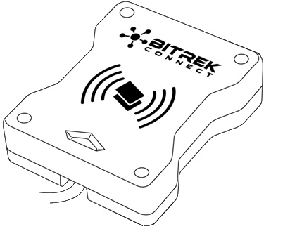
BI CONNECT MF01 module
Device assignment
The BI CONNECT MF01 module of the BITREK CONNECT system is MIFARE Classic standard card reader and is designed for It is used for identification of persons, shift registration, control of fuel refuellings control, etc. The card number received by the module and its status is transmitted to the CONNECT-BUS and can be used by other modules of the BITREK CONNECT system.
Scope of delivery
BI CONNECT MF01 module of the BITREK CONNECT system is available in the following configuration:
- BI CONNECT MF01 module - 1 pc;
- Data sheet - 1 pc;
- Warranty card - 1 pc;
- Packing box - 1 pc.
Technical characteristics of the device
Technical characteristics of the device are presented in Table 1.
Table 1: Technical specifications of the device
| No | Parameters | Characteristics |
|---|---|---|
| 1 | Power supply voltage | 12/24 V |
| 2 | Power consumption (12 V) | 30 mA |
| 3 | connection interface | RS-485, CAN (CONNECT BUS) |
| 4 | Operating frequency | 13.56 MHz |
| 5 | Contactless card type | MIFARE Classic |
| 6 | Maximum number of cards stored in memory | 1 million. |
| 7 | Operating temperature range | -30 °C to +80 °C |
| 8 | Allowable humidity | 80% ± 15% |
| 9 | Dimensions (W × D × H) | 85 × 105 × 30 mm |
| 10 | Net weight | 300 gr. |
| 11 | gross weight | 340 g |
| 12 | casing protection class | IP67 |
Appearance and dimensions of the device
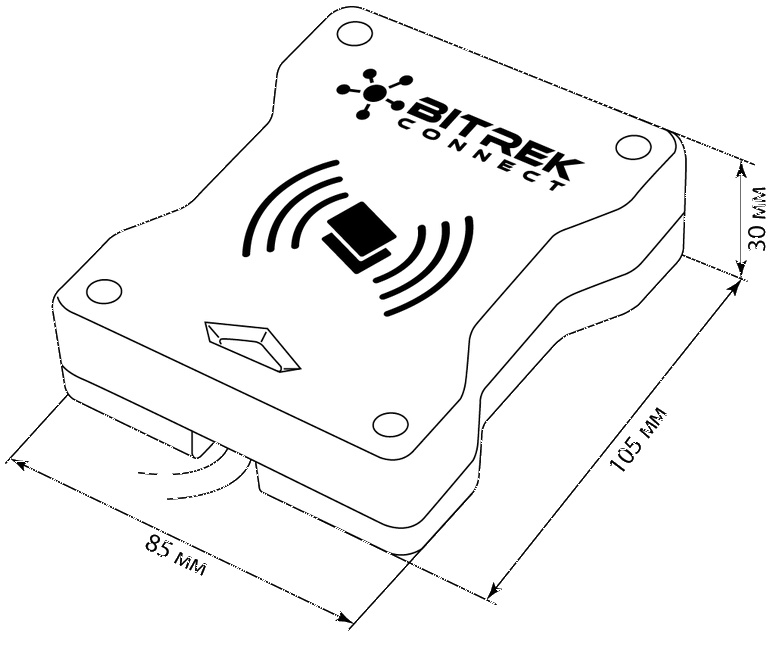
Fig.1. Appearance and dimensions
Pin assignment
Assignment of BI CONNECT MF01 module pins is presented in Table 2.
Table 2. Pin assignment
| No. | Name of contact | Type of signal | Color of wire | Purpose |
|---|---|---|---|---|
| 1 | Vin | Power | White | “+” on-board power (nominal voltage 12 V or 24 V) |
| 2 | GND | power | Gray | common wire (ground) |
| 3 | CAN-H | Input/Output | Pink | CAN-H signal of the CAN interface (CONNECT BUS) |
| 4 | CAN-L | input/output | Brown | CAN-L interface CAN (CONNECT BUS) signal |
| 5 | “A” RS-485 | Input/Output | Yellow | “A” signal of the RS-485 interface |
| 6 | “B” RS-485 | input/output | Green | RS-485 interface “B” signal |
Description of indication organs
There is a light indicator on the front panel of the module, on the front panel of the module which shows the current status of the device.
Table 3: Light indication of the device
| Indicator light color | Description |
|---|---|
| Red | Power is applied to the device. The card is not recognized |
| Yellow | unauthorized card is present on the device. |
| Yellow blinking | Two cards have been swiped at the same time |
| Green | An authorized card has been swiped |
Algorithm of the module
The BI CONNECT MF01 module of the BITREK CONNECT system is compatible with MIFARE cards.
The operation algorithm will depend on the selected mode of the device (ID_Conf 0300).
The operating mode “Card reading key” (is used by default).
When you get the number of the presented card, the module performs searching it in the memory. If the number of the card received is found in the memory, the module transmits to the CONNECT-BUS the number of the received card card and the card status - “own card”. If the code of the received card is not If the code of received card is not found in the memory - the module broadcasts into the CONNECT-BUS the code of received card and its status - “foreign card”.
Operation mode “Key not used”
In this operating mode the module does not verify the card number the presented card with the numbers in the memory and transmits to the CONNECT-BUS Only the unique UID number of the card is transmitted to the CONNECT-BUS. In doing so The card status is always transmitted as “foreign card” and the commands for commands for adding cards to the module memory are ignored.
The status and card number variables are translated in one PGN. The list of all translated variables is presented in the Appendix 1
Configuring the BI CONNECT MF01 module
The BI CONNECT MF01 module has a number of configurable parameters, A list of these can be found in Appendix 1. To configure the module BI CONNECT MF01 module is configured using the system configurator module BITREK CONNECT as well as the CONNECT Configurator software. How to proceed of the configurator module and the software is described in detail in the “Manual for BITREK CONNECT”.
The module can store up to 1 million card numbers cards. To work with the module memory the commands are used, Table 4.
Table 4. List of commands for working with the BI CONNECT MF01 module
| No | Command | Description |
|---|---|---|
| 1 | setparam #### | set parameter value by ID value |
| 2 | getparam #### | query the parameter value by its ID value |
| 3 | saveparam | save parameters to FLASH |
| 4 | addekey | add electronic key |
| 5 | matchekey | search the key in memory with an index |
| 6 | formatekey | delete all the numbers of the electronic key from the memory |
| 7 | clearekey | delete electronic key number |
| 8 | getver | query the software version of the device |
Explanation of the table 4:
Set parameter value by its ID value/request Set parameter value by ID value/request parameter value.
Standard commands for reading and writing parameters of the device. A list of all configurable parameters is given in Appendix 1.
Save parameters to FLASH.
After each change of settings, the module must send the command: saveparam.
After receiving this command, the module sends a response in the form: “PARAM SAVED” and saves the changed parameters in the FLASH memory.
Adding electronic key.
Example command:
addekey XXXXXXXXXX;
where:
addekey - command;
XXXXXXXXXXXX -ID of electronic key, strictly 10 symbols.
In response, the result of the save with the result code is sent. The following variants of response are possible:
“addekey: OK,” - the key is successfully saved to the memory location;
“addekey: MATCH” - key match was found in the cell;
“addekey: ERR,0” - storage failure due to electronic key memory overflow.
Search for the key in the memory.
This command searches the key in the device memory.
An example of the command:
matchekey XXXXXXXXXXXX;
where:
matchekey - command;
XXXXXXXXXXXX - ASCII-encoded key.
In response, the result of the match is sent with the result code result. The following variants of response are possible:
“matchekey: OK,0 >” - match found;
“matchekey: ERR,0>” - no match found.
Remove from the memory all electronic key numbers.
This command is used to erase from the memory all electronic
of electronic keys.
Example command:
formatekey;\\.
The output is sent back in the following format:
“formatekey: OK>” - command executed successfully.
Deleting the specified key number from the memory.
This command locks the specified key number
key number.
Command example:
clearekey XXXXXXXXXXXX;
where:
clearekey - command;
XXXXXXXXXX ASCII coded key\\.
The result is sent back in the following format:
“clearekey: ERR,0” - error on deletion of the specified key number;
“clearekey: OK,0” - the key with the specified number is locked in
{\ “clearekey: OK,0” - the specified key number is blocked in the memory.
Query the software version of the device.
This command retrieves the software version string
of the device.
Example command:
getver;
The response is a string that reads:
“VER: MF01 V1 0003 18”
Adding E-keys to device memory
The string with the value of e-card must contain Strictly 10 characters - numbers 0-9 or capital letters A-F. Each each pair of characters encodes one byte in ASCII representation. The number The card number must be written in hexadecimal (HEX) with a byte-by-by-byte transposition, from least significant byte to most significant byte. The first byte to be written is the low byte of the electronic card, the second is the most significant byte. In a character pair, the first character is the high nibble, The second is the low byte.
Sample of setting:.
The card has its number 8597874069 written on it. First of all, this number must be converted to HEX. After conversion we get the number 200792595.
Then this number must be written into the memory of the module from high byte to low byte. Considering that the length of the key must consist strictly of 10 characters, then the missing character is replaced zero.
The command will look like this: addekey 9525790002;
IMPORTANT.
A special software Mifare Writer is used for card number generation. Mifare Writer software is used for card number generation. In this application number of the generated key is already converted, i.e. no need to do a byte-by-byte rearrangement
Recording procedure for MIFARE Classic cards
Recording of information on MIFARE cards is carried out with the help of BI CONNECT MF01 device, Connect Configurator and Mifare Writer 0.93“ software.
The appearance of the program window is shown in Fig. 2.
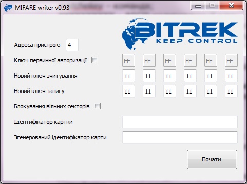
Fig.2 The appearance of the Mifare Writer software.
- Addresses of the device - address of the MF01 module on the CONNECT-BUS;
- Primary authorization key - if this parameter is not checked, then the card reading key is used as standard (FFFFFFFFFFFFFF). If the card reading key was originally changed, it must be specified in this field;
- New reading key - setting a new key for card reading;
- New Write Key - setting a new key to write the card;
- Blocking free sectors - blocking free card memory sectors. Further overwriting of information in these sectors will be impossible.
- Card Identifier - mandatory field. A random number in the range from 1 to 999999, which must be specified. Used in the algorithm for generating the card identifier;
- Generated card identifier - generated card number, rearranged byte by byte. To write the number to the reader memory, this number is written from left to right, without the need for byte-by-by-byte permutation.
List of variables broadcast to the CONNECT-BUS
| No | Parameter name | Width | PGN | Start Bit | Bit Total | Timeout |
|---|---|---|---|---|---|---|
| 1 | Device model | 4 | 18F713 | 0 | 32 | 10 |
| 2 | Software version | 4 | 18F713 | 32 | 32 | 10 |
| 3 | module operating time | 4 | 18F712 | 0 | 32 | 10 |
| 4 | number of restarts | 4 | 18F712 | 32 | 32 | 10 |
| 5 | card status | 1 | 18F701 | 0 | 8 | 5 |
| 6 | card number | 8 | 18F701 | 16 | 40 | 5 |
Note:
The “RFID status” variables can take the following values:
01 - card not detected;
03 - card detected, but not authorized, status “Alien card;
07 - card detected and authorized, status “Friendly card”.
11 - 2 cards installed in reader at the same time
Appendix 1. Device parameters
| No. | Parameter name | ID when configured | Parameter digit | Parameter assignment | Default value |
|---|---|---|---|---|---|
| General | |||||
| 1 | CANSlaveAddr | 0200 | 1 byte | CONNECTBUS device address | 4 |
| 2 | RS485Addr | 0201 | 1 byte | RS-485 bus device address | 9 |
| 3 | DeviceName | 0510 | 1 byte | full device name | MIFARE READER REV001 |
| Periods | |||||
| 4 | CANSendPeriod | 0700 | 2 bytes | Period of sending the main data packet over CAN (msec) | 1001 |
| 5 | CANWaitPeriod | 0701 | 1 byte | valid data hold period on CAN (sec) | 1 |
| MIFARE settings | |||||
| 6 | EkeyPrio | 0300 | 1 byte | key priority (0 - card reading key; 1 - key not used) | 0 |
| 7 | EkeyRead | 0920 | 6 bytes | card reading key | FFFFFFFFFFFFFF |
| Security | |||||
| 8 | DevicePIN | 0910 | 1 byte | terminal password for device access | 11111 |