Module CN03 of the BITREK CONNECT system
Purpose of the device
The CN03 module of Bitrek Connect system is intended for to control technical operating parameters of vehicles equipped with the CAN bus and transmit these parameters to the Connect-Bus. In addition, the module can work with fuel level sensors fuel level sensors, RFID-readers and threshold sensors via interface RS-485.
Package Contents
The CN03 of Bitrek Connect comes with the following configuration:
- CN03 module - 1 pc;
- Data sheet - 1 pc;
- Warranty card - 1 pc;
- Packing box - 1 pc.
- MicroFit 4-pin cable - 1 pc.
- MicroFit 6-pin cable - 1pc.
- Rubber seal - 3 pcs.
Technical characteristics of the device
Technical characteristics of the device are presented in Table 1.
Table 1: Technical specifications of the device
| Parameters | Characteristics |
|---|---|
| Supply voltage | 12 V or 24 V |
| Type of current consumption | (12V) 50mA |
| Interface for connection of fuel level sensors, RFID readers and threshold sensors | RS485 |
| CAN standard | 29 bit (FMS), 11 bit |
| Maximum number of fuel level sensors | 8 |
| Maximum number of RFID readers | 4 |
| Maximum number of threshold sensors | 15 |
| Operating temperature | from -30 °C to +80 °C |
| Allowable humidity | 80 +/- 15% |
| Dimensions (W x L x H) | 78 x 83 x 30 mm |
| Protection class of enclosure | IP44 |
| Net weight | 80 gr. |
| gross weight | 110 g |
Appearance and dimensions of the device
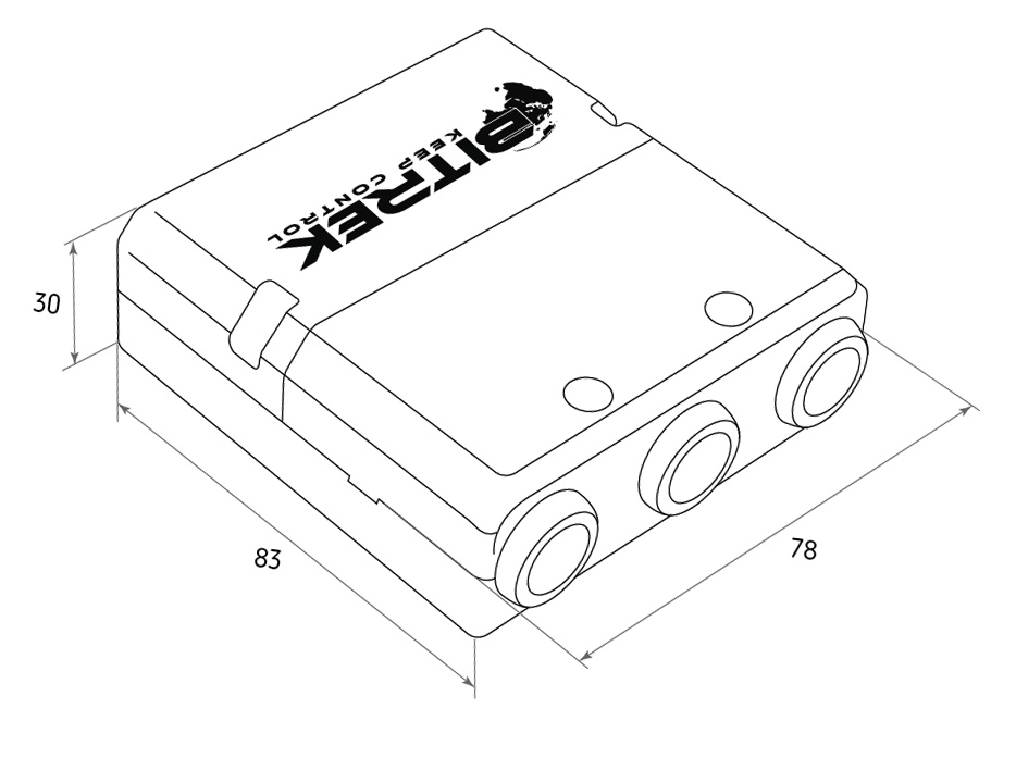
Fig.1. Appearance and dimensions
Pin assignment
The CN03 module is equipped with three Micro-Fit connectors (Fig. 2).
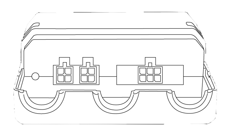
Fig.2. The appearance of the connectors
The four-pin connectors (Fig. 3) are Connect-Bus connectors, which have the power outputs of the module and the outputs signal lines of the bus.
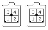
Fig.3. Connect-Bus connectors #1 and #2
The pinout of the Connect-Bus connectors is shown in Table 2.
Table 2 The pin-out of the Connect-Bus connectors No.1 and No.2
| № | Pin name | Signal type | Pin assignment |
|---|---|---|---|
| 1 | GND | Power supply | General lead (ground) |
| 2 | CAN L | Input/output | Signal “CAN_L” of the CAN bus |
| 3 | + Vin | Power supply | “+” On-board power supply (nominal voltage 12 V or 24 V) |
| 4 | CAN H | input/output | Signal “CAN_H” on the CAN bus |
The six-pin connector (Fig.4) is the connector for fuel level sensors, threshold sensors and RFID readers. It has power outputs of sensors, RS485 signal lines and signal lines of the vehicle CAN bus.
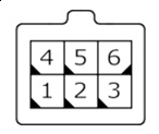
Fig.4. Connector for connecting external devices
The pinout of the connector for connecting external devices is presented in table 3.
Table 3. External device connector pinout
| № | Pin name | Signal type | Pin assignment |
|---|---|---|---|
| 1 | GND | power supply | common ground |
| 2 | CAN H | input/output | CAN_H signal |
| 3 | RS485 A | input/output | RS485 “A” signal |
| 4 | + Vin | Power output | “+” on-board power supply (to power external devices) |
| 5 | CAN L | input/output | “CAN_L” signal on the CAN bus |
| 6 | RS485 B | input/output | RS485 “B” signal |
Description of indications
On the front panel of the module, on the connector side, there are two LEDs on the connector side of the front panel, which indicate the current status of the device.
Red LED - blinks when RS-485 communication is successful
Green LED - lights steadily when the device continuously illuminates when device is successfully started up.
Setting up the CN03 module
The CN03 has a number of configurable parameters of which are listed in Appendix 1. To configure the module module, the Bitrek Connect configurator module is used, as well as Connect Configurator software. How to work with the configurator module and Software are described in detail in the “Guidelines for organizing and configuring Bitrek Connect”.
Configuring the module to work with arbitrary PGN
Parameters FMSPGN00 to FMSPGN19 are used to configure arbitrary PGNs with a bit size of 11 bits or 29 bits expected on the CAN bus of the vehicle and transmitted to the Connect- Bus, with address swapping to the current address of the module on the bus. If parameter is zero, this PGN is considered disabled and is not is considered to be disabled and does not participate in operation. These parameters are set in HEX view and have the following format:
PRIO PGN ADDR.
where:
PRIO - message priority;
PGN is the message body (PGN);
ADDR is the sender's address.
For example: there is a need to set up an arbitrary PGN 18FEE900 (Fuel Consumption: LFC, 1000 mS).
To do this, the value 18FEE900 (Fuel Consumption: LFC: 1000 mS) must be entered in the “Arbitrary PGN00” parameter (ID7800) write the value 18FEE900 (Fig.5). Then set the digit capacity PGN00 parameter is 29 bits, since this PGN is 29- bit (Fig.6). This can be done using the Connect Configurator.
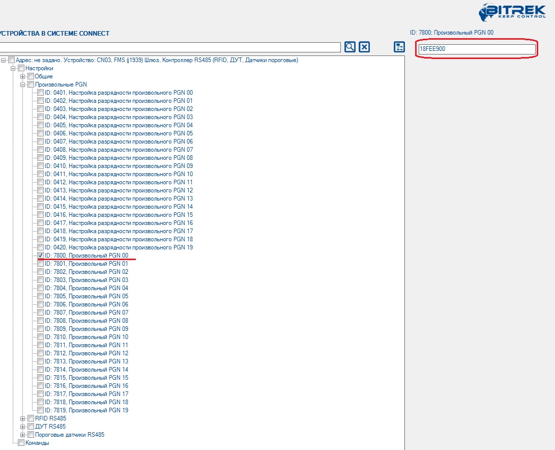
Figure 5. Setting the value of an arbitrary PGN
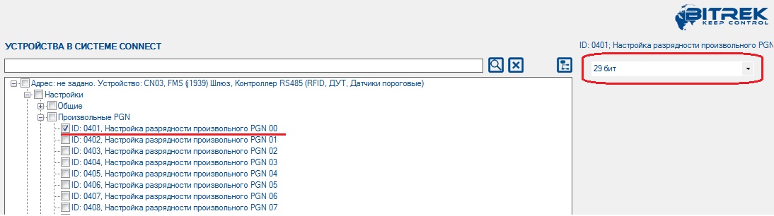
Fig.6. Setting the arbitrary PGN bit value
The CAN reception filter will then be configured to receive messages from CANID 18FEE900. After receiving such a message the current address of the message will be replaced by the peripheral address of the CN03 module and it will be broadcast to the Connect-Bus.
Configuring the module for operation with fuel level sensors
Each fuel level sensor connected to the CN03 module must be preset. The adjustment includes is to assign each sensor on the RS485 bus a network address. After the network addresses of fuel level sensors are assigned, you can configure the CN03 module.
Open the tree-like list of the module parameters by pressing the “+” symbol. The Settings group is displayed in the list. In the subgroup “RS485 remote control unit” you must configure the following parameters: “Address RS485 address” (Fig.7) and “Resolution of RS485 polling” (Fig.8). Parameters “Interval Interrogation period” and “Time of FLS transfer to Connect-Bus” parameters can be left unchanged. leave them unchanged.
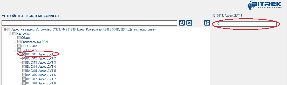
Fig.7. Fuel level sensor address assignment
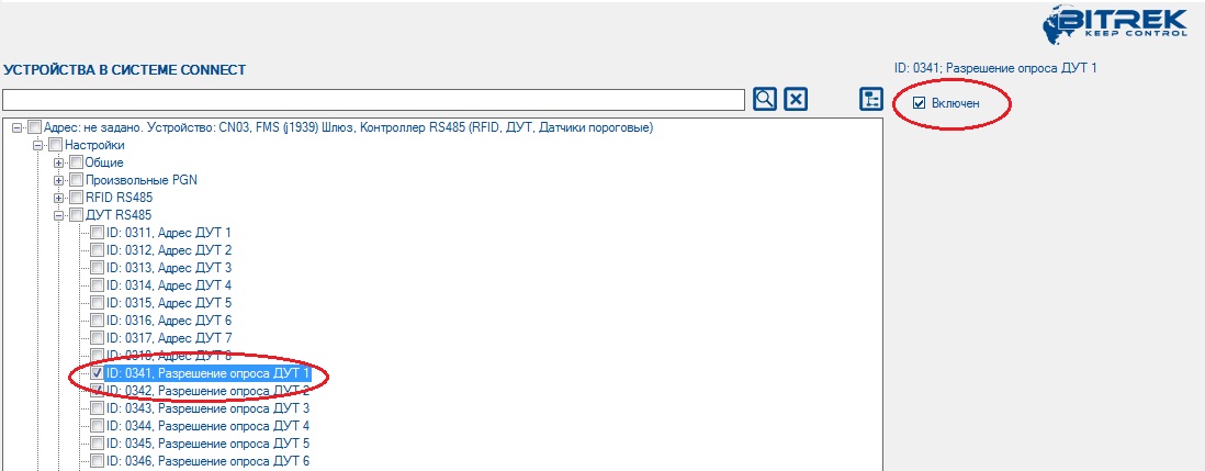
Fig.8. Sensor polling permission
After that the CN03 module will poll the fuel fuel level sensor, which is on the 1st network address on the bus RS485 BUS. The received data message will be translated into the Connect-Bus.
Setting up the module to work with RFID readers
Setting up the module to work with RFID readers the module is configured in the same way. In the “RFID RS485” setting group, you must specify the reader address on the RS485 bus and enable the module to interrogate it. Parameters “RFID polling period” and The “Period of RFID transmission to Connect-Bus” parameters can be left unchanged. parameters can be left unchanged.
Note:
The communication between RFID readers and the CN03 module
according to the RCS SOVA protocol
Configuring the module to work with RS485 threshold sensors
Each threshold sensor connected to the module must must be pre-configured. The configuration comes down to setting up a unique network address on the RS485 bus for each threshold network address on the RS485 bus for each threshold sensor. To configure the network address of the threshold sensors The FL Configurator software is used to set the network address.
Note:.
The network addresses of the threshold sensors must not be the same as
Note: The network addresses of the threshold sensors must not be the same as the network addresses of the fuel level sensors in use.
Then in the subset of the CN03 “Threshold Sensors RS485 sensors” subgroup of the CN03 module settings, you need to enable the sensor polling, specify its network network address on the RS485 bus, specify upper and lower thresholds of operation (Fig.9). These parameters must be configured separately for each of used threshold sensors.
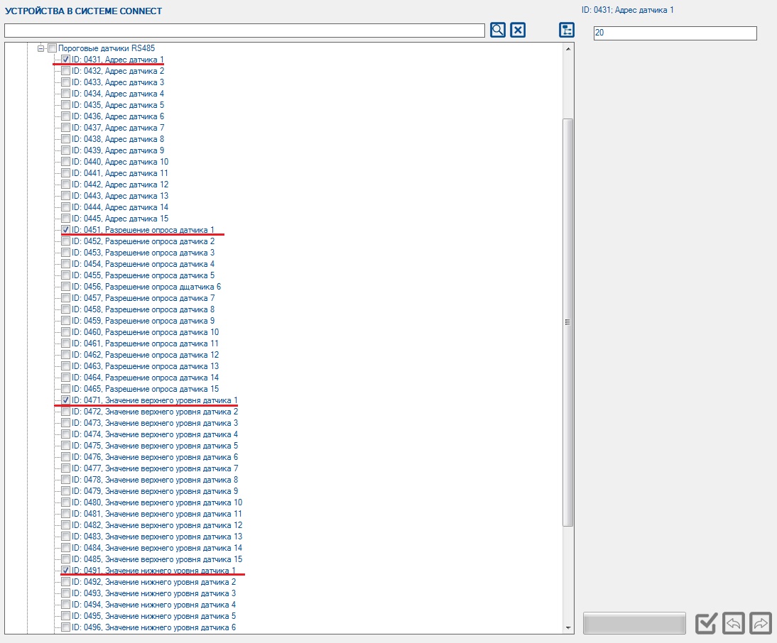
Figure 9. Setting up the RS485 threshold sensors
Up to 15 sensors can be connected to the module simultaneously. In this case it is recommended to allow polling only actually connected sensors. There are 15 parameters in the CN03 settings (id 431 - id 445) to specify the network addresses of the connected sensors. When When specifying the network addresses, the following principle should be followed: The network address of the the net address of the lowermost sensor must be entered in the parameter corresponding to the 1st sensor. the parameter corresponding to the 1st sensor in the CN03 module and then in order.
Note:.
The upper and lower thresholds are set according to
Note: The upper threshold can be adjusted as below.
The “Upper Threshold “ is the sensor value above which the CN03 decides above which the CN03 decides that the sensor has triggered. The value written in this field should be 15- 35% less than the actual value obtained with with the sensor immersed in the grain. This is to ensure that the sensor of the sensor operation.
“Lower threshold “ is the sensor value at which the CN03 module decides that the sensor has gone from the active “triggered” state to the inactive state. The value written in This field should be 15-35% greater than the actual value of the empty sensor.
Sample of setting: Threshold sensors are mounted in the hopper, hopper empty, all sensors have the zero level calibrated at 100 c.u. level. The hopper is then filled with grain so that several sensors are filled. After filling their readings must be recorded. For example: The filled sensors showed a level of 200. In this case, in the “Upper threshold” field you must 170, and in the “Lower Threshold” field - 130.
Preset PGNs of FMS standard
The CN03 module has a group of preset FMS standard PGNs (J1939) that are monitored and transmitted to the Connect- Bus always, regardless of the settings of the arbitrary PGNs. A list of such PGNs are listed in Table 4.
The principle of operation of the device is as follows: The module receives all messages whose CANID contains a PGN from the list of preset list, ignoring the priority of the message and the ignoring the priority of the message and the sender address. The received CANIDs are transmitted to the Connect-Bus with priority 0x18 and the address of the CN03 module.
Table 4. List of preset PGNs
| No. | PGN | Description |
|---|---|---|
| 1 | 0x18FEE900 | amount of fuel used |
| 2 | 0x18FEFC00 | Fuel level |
| 3 | 0x18FEF200 | hourly fuel consumption |
| 4 | 0x18FEF200 | Instantaneous fuel economy |
| 5 | 0x18FD0900 | High-resolution fuel consumption total |
| 6 | 0x18F00400 | Engine RPMs |
| 7 | 0x18F00400 | Actual engine torque |
| 8 | 0x18FEE500 | Engine running time |
| 9 | 0x18FEEE00 | engine coolant temperature |
| 10 | 0x18F00300 | engine load percentage at current speed |
| 11 | 0x18F00500 | Gearbox current gearbox |
| 12 | 0x18F00500 | Selected transmission gear |
| 13 | 0x18FEE800 | Compass bearing |
| 14 | 0x18FEE800 | GPS/GLONASS speed |
| 15 | 0x18FEE800 | GPS/GLONASS angle deviation |
| 16 | 0x18FEE800 | GPS altitude |
| 17 | 0x18FEF300 | Latitude |
| 18 | 0x18FEF300 | Longitude |
| 19 | 0x18FEC100 | Vehicle Mileage |
| 20 | 0x18FEF500 | Ambient temperature |
| 21 | 0x18FEF100 | Vehicle speed determined by the rotation of the wheels |
| 22 | 0x18FEF100 | clutch pedal |
| 23 | 0x18FEF100 | brake pedal |
| 24 | 0x18FEF100 | cruise control |
| 25 | 0x18F00300 | Accelerator pedal position 1 |
| 26 | 0x18FE7000 | Total vehicle weight |
| 27 | 0x18FEF100 | parking brake switch |
| 28 | 0x18FE4E00 | Door position 2 |
| 29 | 0x18FE4E00 | Door position |
List of variables broadcast to the CONNECT-BUS
| № | Parameter Name | Size | PGN | Start Bit | Bit Total | Time Out |
|---|---|---|---|---|---|---|
| Systems | ||||||
| 1 | Device model | 4 | 18F713 | 0 | 32 | 10 |
| 2 | software version | 4 | 18F713 | 32 | 32 | 10 |
| 3 | module operating time | 4 | 18F712 | 0 | 32 | 10 |
| 4 | number of module restarts | 4 | 18F712 | 32 | 32 | 10 |
| CAN J1939 (FMS Standard) | ||||||
| 5 | Fuel consumption | 4 | 18FEE9 | 32 | 32 | 0 |
| 6 | Fuel level 1 | 1 | 18FEFC | 8 | 8 | 0 |
| 7 | hourly fuel consumption | 2 | 18FEF2 | 0 | 16 | 5 |
| 8 | Instantaneous fuel economy | 2 | 18FEF2 | 16 | 16 | 5 |
| 9 | High-resolution fuel economy | 4 | 18FD09 | 32 | 32 | 0 |
| 10 | engine rpm | 2 | 18F004 | 24 | 16 | 5 |
| 11 | motor running time | 4 | 18FEE5 | 0 | 32 | 0 |
| 12 | Engine coolant temperature | 1 | 18FEEE | 0 | 8 | 5 |
| 13 | Engine load percentage at current speed | 1 | 18F003 | 16 | 8 | 5 |
| 14 | actual engine torque | 1 | 18F004 | 16 | 8 | 5 |
| 15 | current gearbox | 1 | 18F005 | 24 | 8 | 5 |
| 16 | selected gearbox | 1 | 18F005 | 0 | 8 | 5 |
| 17 | Compass azimuth | 2 | 18FEE8 | 0 | 16 | 0 |
| 18 | GPS/GLONASS speed | 2 | 18FEE8 | 16 | 16 | 0 |
| 19 | GPS/GLONASS angle deviation | 2 | 18FEE8 | 32 | 16 | 0 |
| 20 | GPS/GLONASS altitude | 2 | 18FEE8 | 48 | 16 | 0 |
| 21 | GPS/GLONASS latitude | 4 | 18FEF3 | 0 | 32 | 0 |
| 22 | GPS/GLONASS Longitude | 4 | 18FEF3 | 32 | 32 | 0 |
| 23 | Vehicle Mileage | 4 | 18FEC1 | 0 | 32 | 0 |
| 24 | ambient temperature | 2 | 18FEF5 | 24 | 16 | 5 |
| 25 | Vehicle speed determined by the movement of the wheels | 2 | 18FEF1 | 8 | 16 | 5 |
| 26 | Clutch pedal | 1 | 18FEF1 | 30 | 2 | 5 |
| 27 | brake pedal | 1 | 18FEF1 | 28 | 2 | 5 |
| 28 | cruise control | 1 | 18FEF1 | 24 | 2 | 5 |
| 29 | Accelerator pedal position 1 | 1 | 18F003 | 8 | 8 | 5 |
| 30 | Total weight of the vehicle | 2 | 18FEF70 | 16 | 16 | 0 |
| 31 | parking brake switch | 1 | 18FEF1 | 2 | 2 | 0 |
| 32 | Door position 2 | 1 | 18FE4E | 6 | 2 | 0 |
| 33 | door position | 1 | 18FE4E | 0 | 4 | 0 |
| DROPPED RS485 | ||||||
| 38 | FLS status 1 | 1 | 18F709 | 0 | 1 | 10 |
| 39 | FLS 2 status | 1 | 18F70A | 0 | 1 | 10 |
| 40 | FLS 3 status | 1 | 18F70B | 0 | 1 | 10 |
| 41 | FLS 4 status | 1 | 18F70C | 0 | 1 | 10 |
| 42 | FLS 5 status | 1 | 18F70D | 0 | 1 | 10 |
| 43 | FLS status 6 | 1 | 18F70E | 0 | 1 | 10 |
| 44 | FLS 7 status | 1 | 18F70F | 0 | 1 | 10 |
| 45 | FLS status 8 | 1 | 18F710 | 0 | 1 | 10 |
| 46 | Temperature of FLS 1 | 1 | 18F709 | 16 | 8 | 10 |
| 47 | Temperature of FLS 2 | 1 | 18F70A | 16 | 8 | 10 |
| 48 | Temperature of FLS 3 | 1 | 18F70B | 16 | 8 | 10 |
| 49 | Temperature of FLS 4 | 1 | 18F70C | 16 | 8 | 10 |
| 50 | Temperature of FLS 5 | 1 | 18F70D | 16 | 8 | 10 |
| 51 | Temperature of FLS 6 | 1 | 18F70E | 16 | 8 | 10 |
| 52 | Temperature of FLS 7 | 1 | 18F70F | 16 | 8 | 10 |
| 53 | FLS 8 temperature | 1 | 18F710 | 16 | 8 | 10 |
| 54 | Fuel FLS 1 | 2 | 18F709 | 24 | 16 | 10 |
| 55 | FLS fuel 2 | 2 | 18F70A | 24 | 16 | 10 |
| 56 | FLS fuel 3 | 2 | 18F70B | 24 | 16 | 10 |
| 57 | FLS fuel 4 | 2 | 18F70C | 24 | 16 | 10 |
| 58 | FLS fuel 5 | 2 | 18F70D | 24 | 16 | 10 |
| 59 | FLS fuel 6 | 2 | 18F70E | 24 | 16 | 10 |
| 60 | FLS fuel 7 | 2 | 18F70F | 24 | 16 | 10 |
| 61 | Fuel FLS 8 | 2 | 18F710 | 24 | 16 | 10 |
| RFID RS485 | ||||||
| 62 | RFID status 1 | 1 | 18F701 | 0 | 2 | 5 |
| 63 | RFID status 2 | 1 | 18F702 | 0 | 2 | 5 |
| 64 | RFID status 3 | 1 | 18F703 | 0 | 2 | 5 |
| 65 | RFID Status 4 | 1 | 18F704 | 0 | 2 | 5 |
| 66 | RFID card number 1 | 8 | 18F701 | 16 | 40 | 5 |
| 67 | RFID card number 2 | 8 | 18F702 | 16 | 40 | 5 |
| 68 | RFID card number 3 | 8 | 18F703 | 16 | 40 | 5 |
| 69 | RFID card number 4 | 8 | 18F704 | 16 | 40 | 5 |
| RS485 threshold sensors | ||||||
| 70 | Level bitmask | 2 | 18F720 | 0 | 16 | 5 |
| 71 | grain level | 2 | 18F720 | 16 | 16 | 5 |
| 72 | Upper threshold | 2 | 18F720 | 32 | 16 | 5 |
| 73 | bitmask of allowed sensors | 2 | 18F721 | 0 | 16 | 5 |
| 74 | Bit mask of connected sensors | 2 | 18F721 | 16 | 16 | 5 |
| 75 | Threshold sensor 1 on RS485 bus | 1 | 18F731 | 0 | 8 | 5 |
| 76 | Threshold sensor 2 on the RS485 bus | 1 | 18F732 | 0 | 8 | 5 |
| 77 | Threshold sensor 3 on the RS485 bus | 1 | 18F733 | 0 | 8 | 5 |
| 78 | RS485 bus threshold sensor 4 | 1 | 18F734 | 0 | 8 | 5 |
| 79 | RS485 bus threshold sensor 5 | 1 | 18F735 | 0 | 8 | 5 |
| 80 | RS485 bus threshold sensor 6 | 1 | 18F736 | 0 | 8 | 5 |
| 81 | RS485 bus threshold sensor 7 | 1 | 18F737 | 0 | 8 | 5 |
| 82 | RS485 bus threshold sensor 8 | 1 | 18F738 | 0 | 8 | 5 |
| 83 | RS485 bus threshold sensor 9 | 1 | 18F739 | 0 | 8 | 5 |
| 84 | RS485 bus threshold sensor 10 | 1 | 18F73A | 0 | 8 | 5 |
| 85 | RS485 bus threshold sensor 11 | 1 | 18F73B | 0 | 8 | 5 |
| 86 | RS485 bus threshold sensor 12 | 1 | 18F73C | 0 | 8 | 5 |
| 87 | RS485 bus threshold sensor 13 | 1 | 18F73D | 0 | 8 | 5 |
| 88 | RS485 bus threshold sensor 14 | 1 | 18F73E | 0 | 8 | 5 |
| 89 | RS485 bus threshold sensor 15 | 1 | 18F73F | 0 | 8 | 5 |
| 90 | State of sensor 1 | 1 | 18F731 | 8 | 8 | 5 |
| 91 | State of sensor 2 | 1 | 18F732 | 8 | 8 | 5 |
| 92 | State of sensor 3 | 1 | 18F733 | 8 | 8 | 5 |
| 93 | Sensor 4 condition | 1 | 18F734 | 8 | 8 | 5 |
| 94 | Sensor 5 condition | 1 | 18F735 | 8 | 8 | 5 |
| 95 | Sensor 6 condition | 1 | 18F736 | 8 | 8 | 5 |
| 96 | sensor 7 condition | 1 | 18F737 | 8 | 8 | 5 |
| 97 | Sensor 8 condition | 1 | 18F738 | 8 | 8 | 5 |
| 98 | Sensor 9 condition | 1 | 18F739 | 8 | 8 | 5 |
| 99 | Sensor 10 condition | 1 | 18F73A | 8 | 8 | 5 |
| 100 | Sensor 11 condition | 1 | 18F73B | 8 | 8 | 5 |
| 101 | State of sensor 12 | 1 | 18F73C | 8 | 8 | 5 |
| 102 | State of sensor 13 | 1 | 18F73D | 8 | 8 | 5 |
| 103 | Sensor 14 | 1 | 18F73E | 8 | 8 | 5 |
| 104 | Sensor 15 | 1 | 18F73F | 8 | 8 | 5 |
| 105 | Temperature sensor 1 | 1 | 18F731 | 16 | 8 | 5 |
| 106 | Temperature sensor 2 | 1 | 18F732 | 16 | 8 | 5 |
| 107 | Temperature sensor 3 | 1 | 18F733 | 16 | 8 | 5 |
| 108 | Temperature sensor 4 | 1 | 18F734 | 16 | 8 | 5 |
| 109 | Temperature sensor 5 | 1 | 18F735 | 16 | 8 | 5 |
| 110 | Temperature sensor 6 | 1 | 18F736 | 16 | 8 | 5 |
| 111 | temperature sensor 7 | 1 | 18F737 | 16 | 8 | 5 |
| 112 | temperature sensor 8 | 1 | 18F738 | 16 | 8 | 5 |
| 113 | temperature sensor 9 | 1 | 18F739 | 16 | 8 | 5 |
| 114 | temperature sensor 10 | 1 | 18F73A | 16 | 8 | 5 |
| 115 | temperature sensor 11 | 1 | 18F73B | 16 | 8 | 5 |
| 116 | temperature sensor 12 | 1 | 18F73C | 16 | 8 | 5 |
| 117 | Temperature sensor 13 | 1 | 18F73D | 16 | 8 | 5 |
| 118 | temperature sensor 14 | 1 | 18F73E | 16 | 8 | 5 |
| 119 | Sensor temperature 15 | 1 | 18F73F | 16 | 8 | 5 |
| 120 | Sensor level 1 | 2 | 18F731 | 24 | 16 | 5 |
| 121 | Sensor level 2 | 2 | 18F732 | 24 | 16 | 5 |
| 122 | Sensor level 3 | 2 | 18F733 | 24 | 16 | 5 |
| 123 | Sensor level 4 | 2 | 18F734 | 24 | 16 | 5 |
| 124 | Sensor level 5 | 2 | 18F735 | 24 | 16 | 5 |
| 125 | Sensor level 6 | 2 | 18F736 | 24 | 16 | 5 |
| 126 | Sensor level 7 | 2 | 18F737 | 24 | 16 | 5 |
| 127 | Sensor level 8 | 2 | 18F738 | 24 | 16 | 5 |
| 128 | Sensor level 9 | 2 | 18F739 | 24 | 16 | 5 |
| 129 | Sensor level 10 | 2 | 18F73A | 24 | 16 | 5 |
| 130 | Sensor level 11 | 2 | 18F73B | 24 | 16 | 5 |
| 131 | Sensor level 12 | 2 | 18F73C | 24 | 16 | 5 |
| 132 | Sensor level 13 | 2 | 18F73D | 24 | 16 | 5 |
| 133 | Sensor level 14 | 2 | 18F73E | 24 | 16 | 5 |
| 134 | Sensor level 15 | 2 | 18F73F | 24 | 16 | 5 |
| 135 | Sensor polling resolution 1 | 1 | 18F731 | 56 | 8 | 5 |
| 136 | Sensor polling resolution 2 | 1 | 18F732 | 56 | 8 | 5 |
| 137 | Sensor 3 polling resolution | 1 | 18F733 | 56 | 8 | 5 |
| 138 | Sensor polling resolution 4 | 1 | 18F734 | 56 | 8 | 5 |
| 139 | Sensor polling resolution 5 | 1 | 18F735 | 56 | 8 | 5 |
| 140 | Sensor polling resolution 6 | 1 | 18F736 | 56 | 8 | 5 |
| 141 | Sensor polling resolution 7 | 1 | 18F737 | 56 | 8 | 5 |
| 142 | Sensor polling resolution 8 | 1 | 18F738 | 56 | 8 | 5 |
| 143 | Sensor polling resolution 9 | 1 | 18F739 | 56 | 8 | 5 |
| 144 | Sensor polling resolution 10 | 1 | 18F73A | 56 | 8 | 5 |
| 145 | Sensor polling resolution 11 | 1 | 18F73B | 56 | 8 | 5 |
| 146 | Sensor polling resolution 12 | 1 | 18F73C | 56 | 8 | 5 |
| 147 | Sensor polling resolution 13 | 1 | 18F73D | 56 | 8 | 5 |
| 148 | Sensor polling resolution 14 | 1 | 18F73E | 56 | 8 | 5 |
| 149 | Sensor polling resolution 15 | 1 | 18F73F | 56 | 8 | 5 |
Supplement 1. Device parameters
| Parameter name | ID when configured | Parameter digit | Parameter assignment | Default value |
|---|---|---|---|---|
| General | ||||
| CANSlaveAddr | 0200 | 1 byte | device address on CONNECTBUS | 1 |
| DevicePIN | 0400 | 4 bytes | Device access password | 11111 |
| CANSpeed | 0201 | 1 byte | CAN speed setting | 250 kbit\s |
| Arbitrary PGN | ||||
| PGNBitSize00 - PGNBitSize19 | 0401 - 0420 | 1 byte | 1 byte Setting the arbitrary PGN bit rate | 0 (off) |
| FMSPGN00 - FMSPGN19 | 7800 - 7819 | 4 bytes | PGN translated from vehicle CAN bus to CONNECT-BUS | 0 (off) |
| RFID RS485 | ||||
| AddrSova1 - AddrSova4 | 0211 - 0214 | 1 byte | RFID SOVA address on the RS485 bus | 1 - 4 |
| Sova1Ena - Sova4Ena | 0241 - 0244 | 1 byte | SOVA RFID polling permission | 1 |
| GetPeriodSova1 - GetPeriodSova4 | 0261 - 0264 | 2 bytes | SOVA RFID polling period (*100 ms) | 100 (10 seconds) |
| SendPeriodSova1 - SendPeriodSova4 | 0281 - 0284 | 2 bytes | Period of sending RFID SOVA to CONNECT BUS (*100 ms) | 10 (1 second) |
| RS485 REMOTE CONTROL | ||||
| Fuel1Addr - Fuel8Addr | 0311 - 0318 | 1 byte | RS485 bus address | 11 - 18 |
| Fuel1Ena - Fuel8Ena | 0341 - 0348 | 1 byte | Resolution of the FLS poll | 1 |
| GetPeriodFuel1 - GetPeriodFuel8 | 0361 - 0368 | 2 bytes | RTC polling period (*100 ms) | 100 (10 seconds) |
| SendPeriodFuel1 - SendPeriodFuel8 | 0381 - 0388 | 2 bytes | period to send the RTC values to the CONNECT-BUS | 10 (1 second) |
| RS485 threshold sensors | ||||
| AddrSens1 - AddrSens15 | 0431 - 0445 | 1 byte | RS485 threshold sensor address | 20 - 34 |
| Sens1Ena - Sens15Ena | 0451 - 0465 | 1 byte | Threshold sensor polling permission | 0 (off) |
| Sens1UpLimit - Sens15UpLimit | 0471 - 0485 | 2 bytes | Threshold sensor upper level value | 170 |
| Sens1DownLimit - Sens15DownLimit | 0491 - 0505 | 2 bytes | value of low level threshold sensor | 120 |
| GetPeriodSens1 - GetPeriodSens15 | 0397 | 2 bytes | polling period of all threshold sensors (*100 ms) | 100 (10 seconds) |
| SendPeriodSens1 - SendPeriodSens15 | 0398 | 2 bytes | Period of sending values of all threshold sensors to the CONNECTBUS (*100 ms) | 10 (1 second) |