Table of Contents
Quick start on mNVR BITREK connection

Complete set
In the box you will find:
- mNVR BITREK device
- Warranty card
- GPS antenna
- Wifi antenna
- 2 LTE antennas
- Power cord
- CONNECT bus cable
- Cable sensors
- Wrench

Connection
- Using a wrench, unscrew the screws and remove the spare bar:
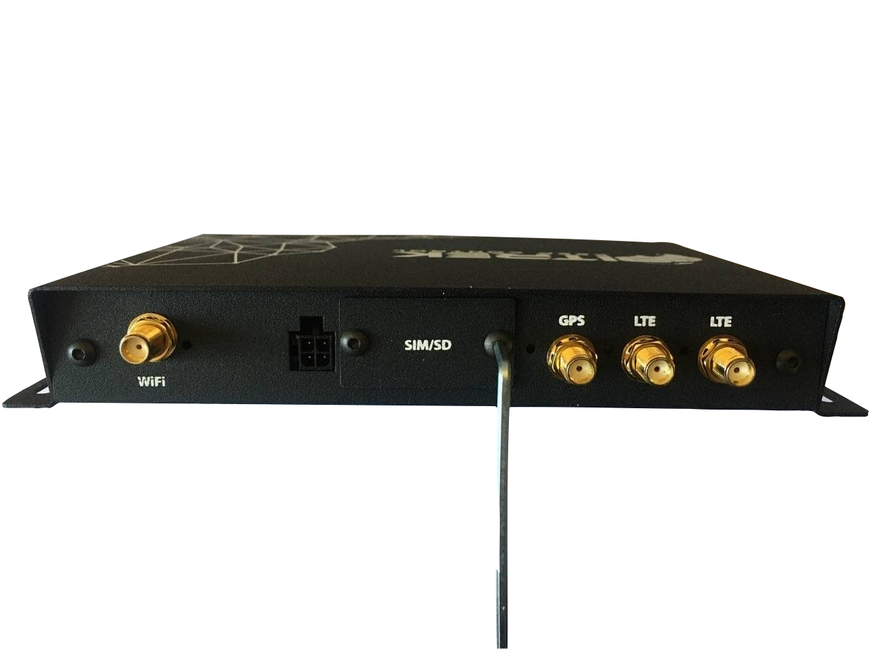
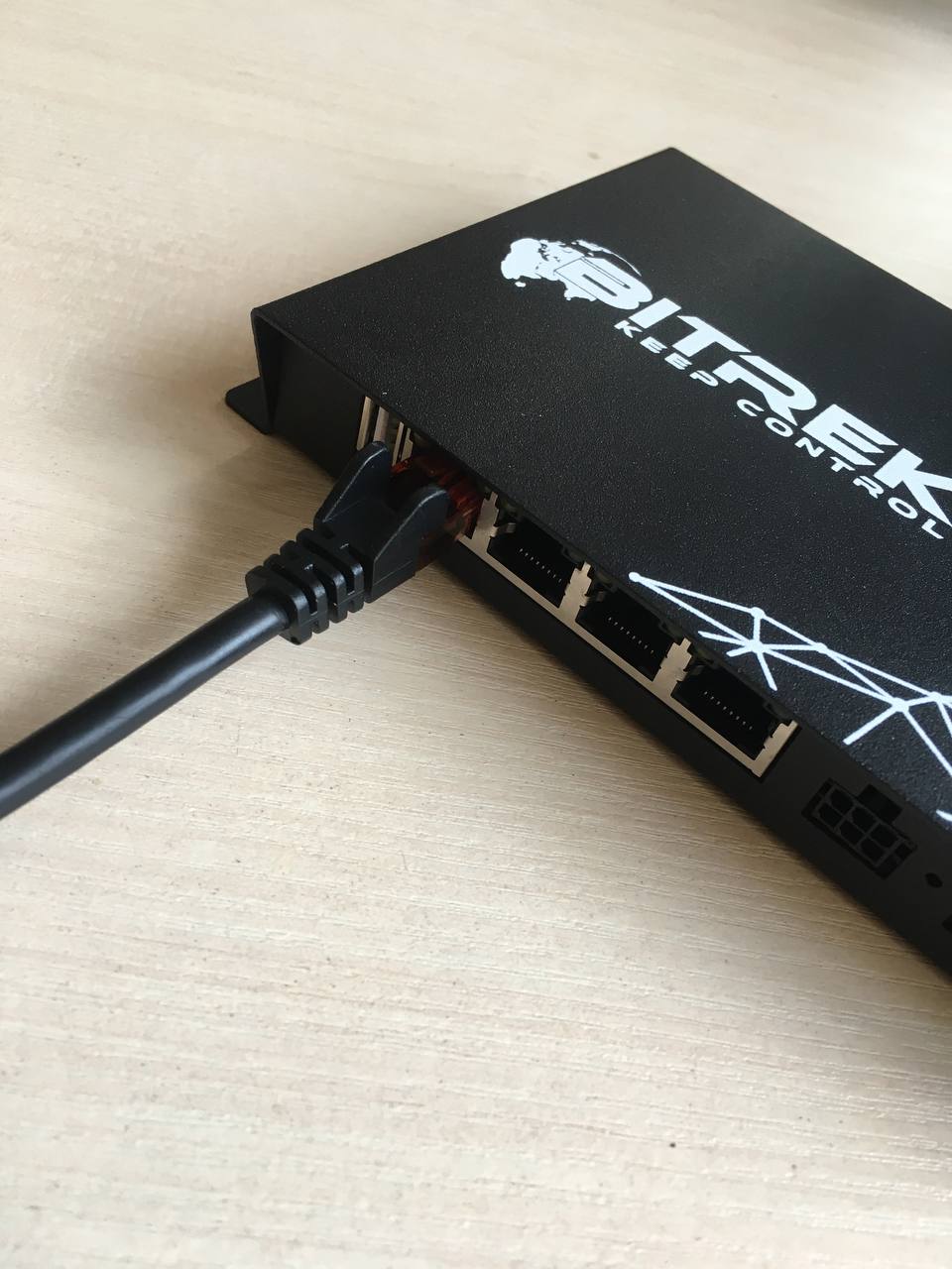
- After installing the SIM card, connect the antennas to the device:

- After connecting the antennas to the device, you need to connect it to the power supply

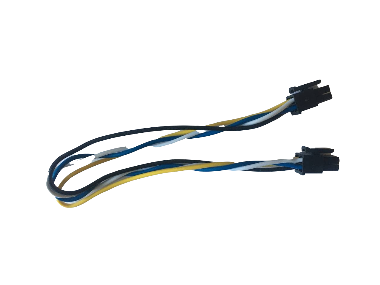
- If you need to connect it to the CONNECT bus then use the following cable
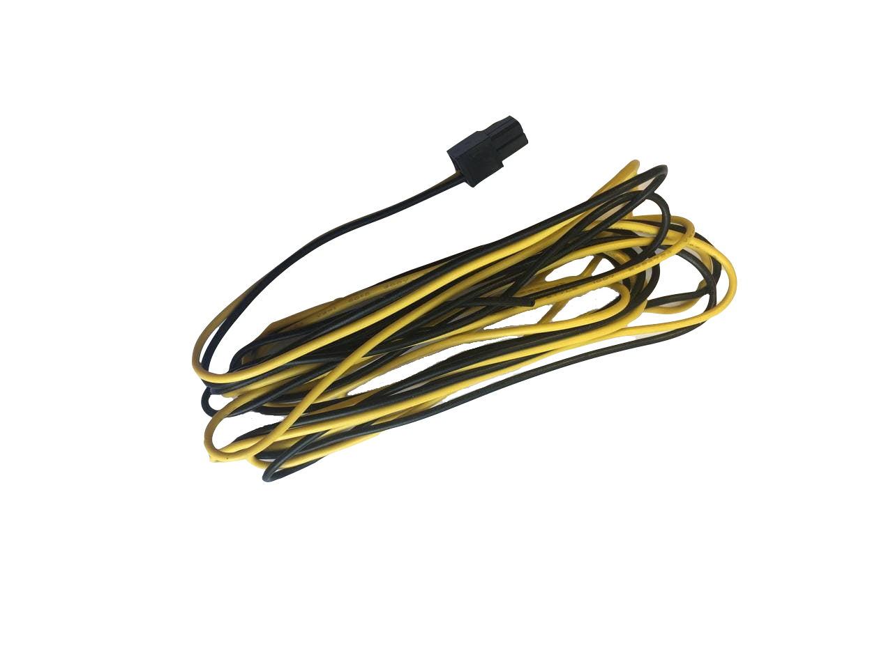
- If before 12V power then use the following cable (yellow +, black -)
Example of power connection: 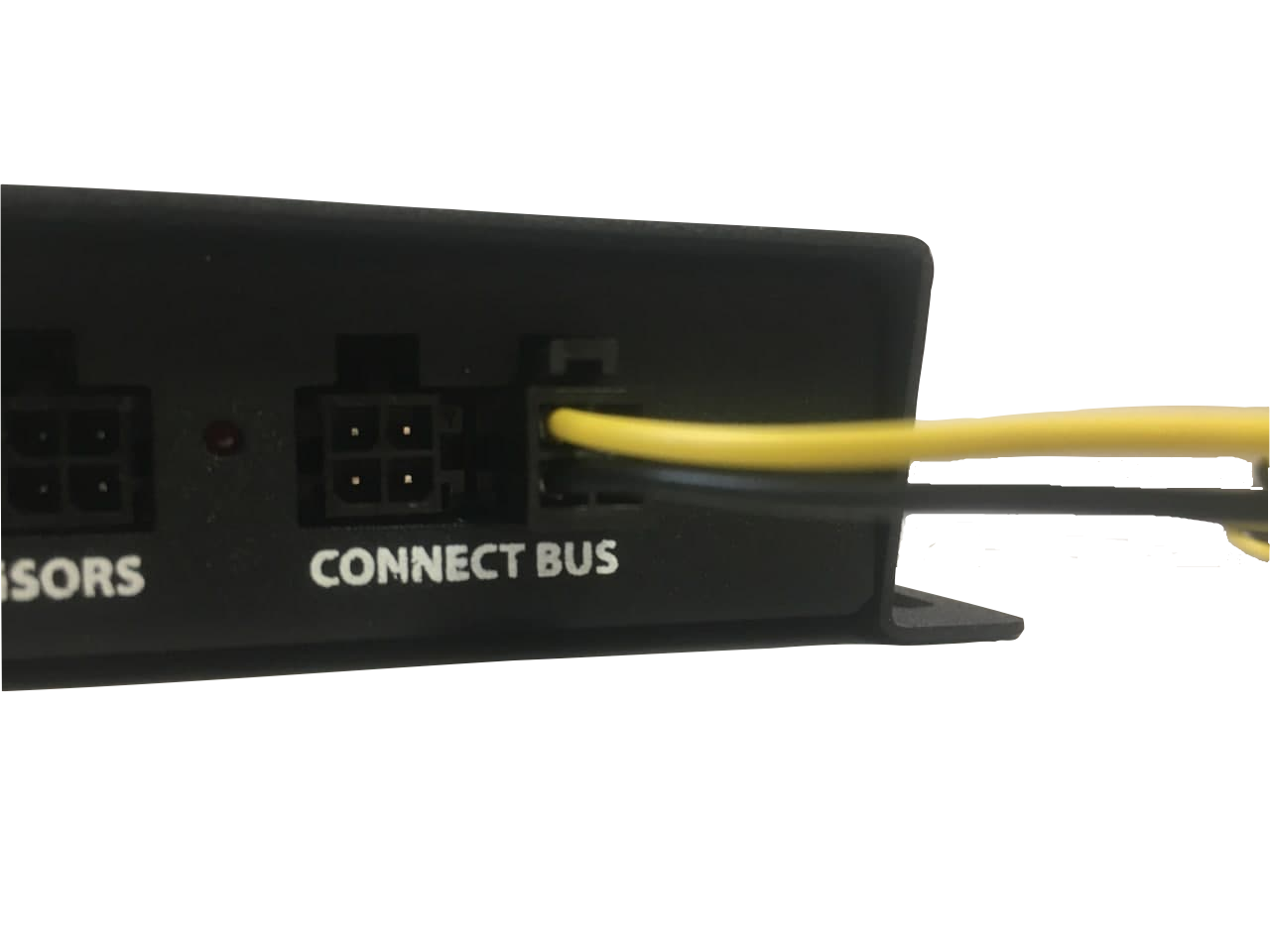
After connecting to the power supply, it takes 1-2 minutes to download the device.
After downloading, make sure that the indication was successful
| Indicator color | Location | Value | Status |
|---|---|---|---|
| red | from the cameras | CAN power and status indicator | should be lit continuously if CAN is connected, flashes if CAN is not connected, if not lit - then power problems or CAN |
| blue | from the antennas | Wi-Fi indicator | first blinks frequently searching for a network, then blinks less often if an access point is found |
| yellow | from the antennas | Internet indicator | glows in the presence of the Internet |
| green | from the antennas | GPS indicator | Does not glow in the absence of GPS |
| orange | from the antennas | Modem indicator | flashing |
Getting Started
After connecting the device to the power supply, it must be connected to the Internet. You can do this in two ways:
- Using Wi-Fi;
- With the help of the cloud.
- The first way: Using WI-Fi
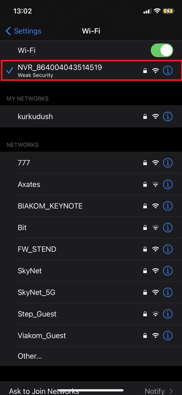
- find the Wi-Fi device in the list (NVR_IMEI-unique device number)
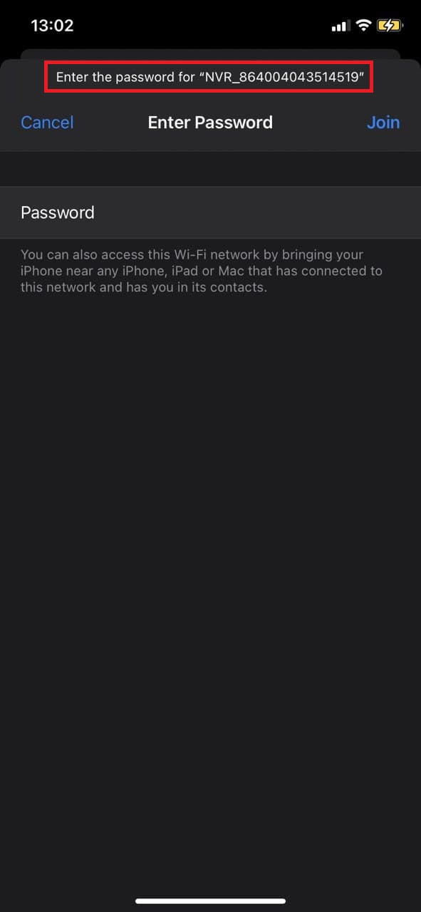
- Then enter the password to Wi-Fi which is printed on the sticker of the device passport, in our case it is “NVR12345”
- If everything is done correctly, we will see that connected to the network:

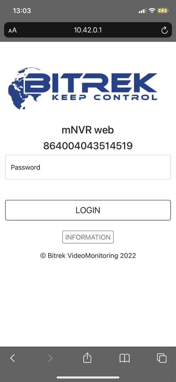
- Then enter the address “10.42.0.1” in your browser, enter the password and go to the device control menu (On some models of phones, the connection may not be immediate. In this case, you need to wait about 30 seconds and try again)
- The second way: Using the cloud service https://device.bitrek.video/
- Go to the site enter the IMEI and password that is printed on the sticker of the device passport:

Done! We are in the device management menu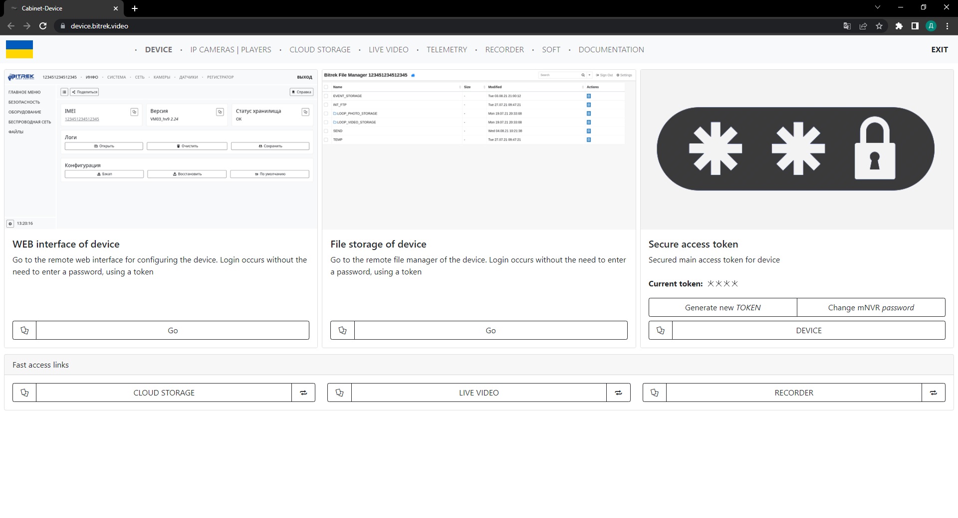
Working with the WEB interface
Go to the WEB interface page of the device by clicking on the corresponding icon on the photo
Here we can see the main tabs such as: INFO, SYSTEM, NETWORK, CAMERAS, SENSORS, RECORDER and auxiliary tabs for each of the sections located on the left. Let's go through each of the tabs briefly
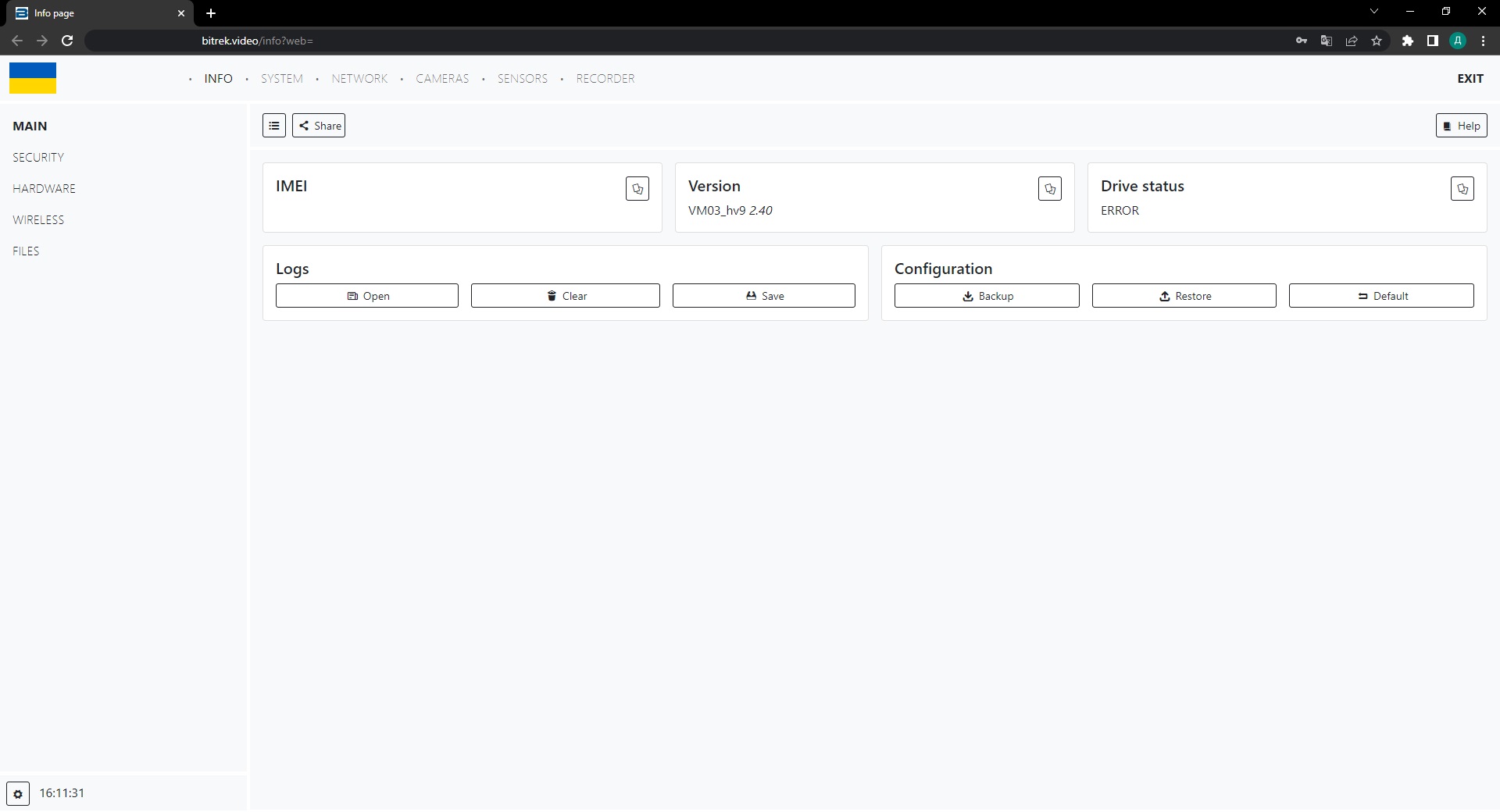
INFO
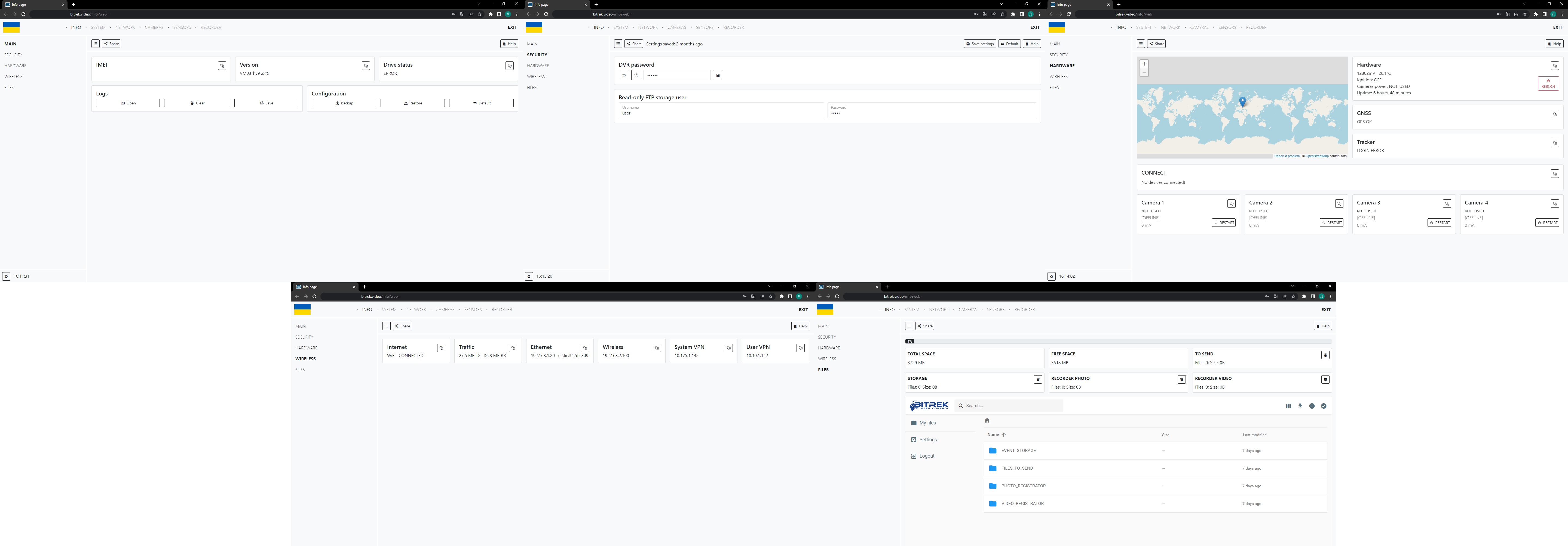 (click on the image for detailed view)
This tab is mainly for:
- Viewing information about your device;
- Logs of your device;
- Device configuration with the ability to download and transfer to other devices;
- Change the password of your device for security purposes;
- View files in the storage of your device.
SYSTEM
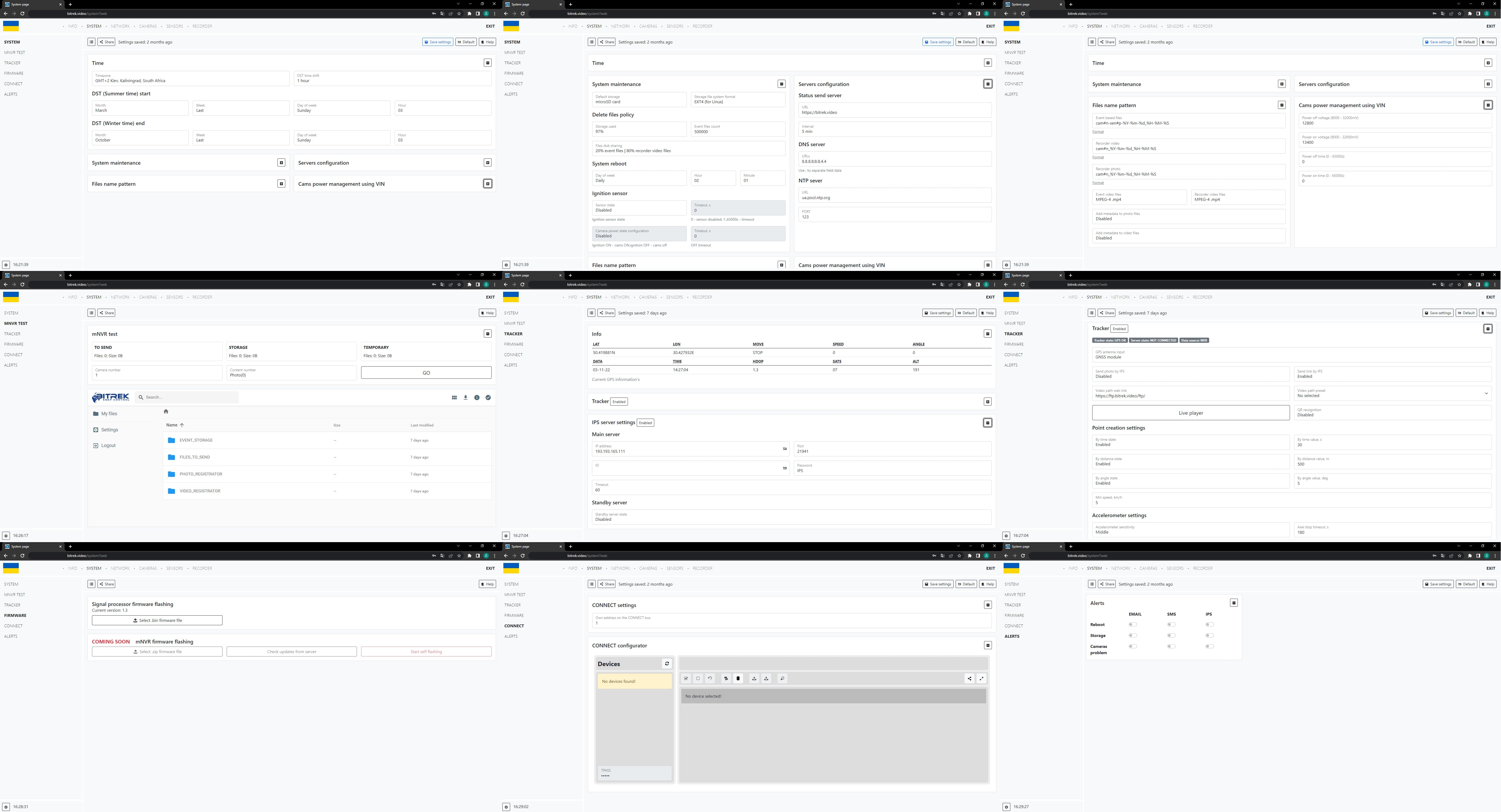 (click on the image for detailed view)
The tab is intended for device system settings such as
- Date and time;
- Storage usage;
- Server configuration;
- File name patterns;
- Camera power management by VIN;
- Device testing;
- Updating the processor of the device;
- Tracker;
- IPS server;
- Setting up trackers through the CONNECT system;
- Receiving notifications (Email, SMS, IPS).
NETWORK
 (click on the image for detailed view)
The tab is intended for device network settings such as:
- Event servers for FTP and for photo and video registrar;
- VPN configuration settings;
- Wi-Fi configuration and access point settings;
- LAN network settings;
- GSM/LTE network settings and traffic usage;
- Email settings.
CAMERAS
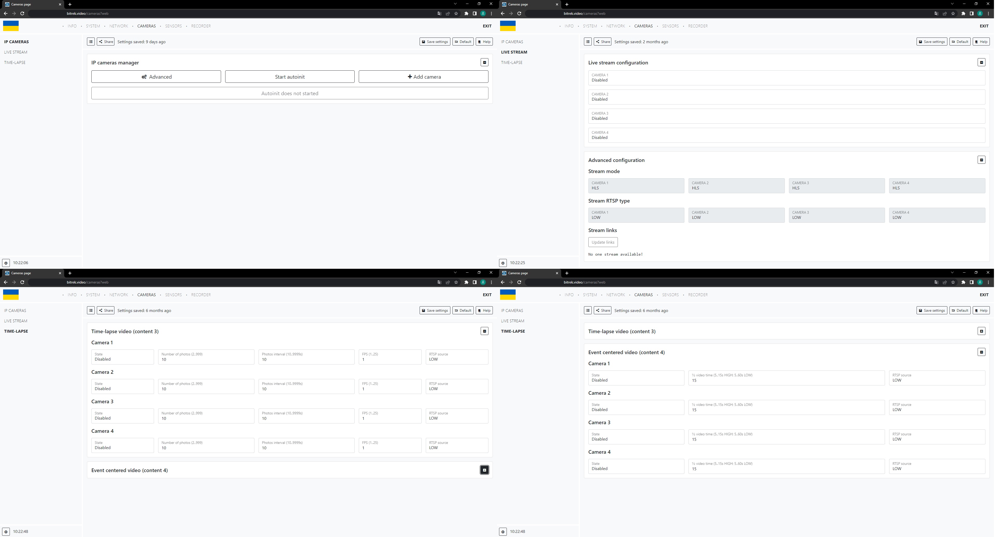 (click on the image for detailed view)
This section allows:
- Add cameras;
- View the list of available cameras;
- View live broadcast using cameras;
- Set up timelapse and video with the event in the center.
SENSORS

The section allows you to work with sensors, namely to add, edit and work with different types of sensors
RECORDER
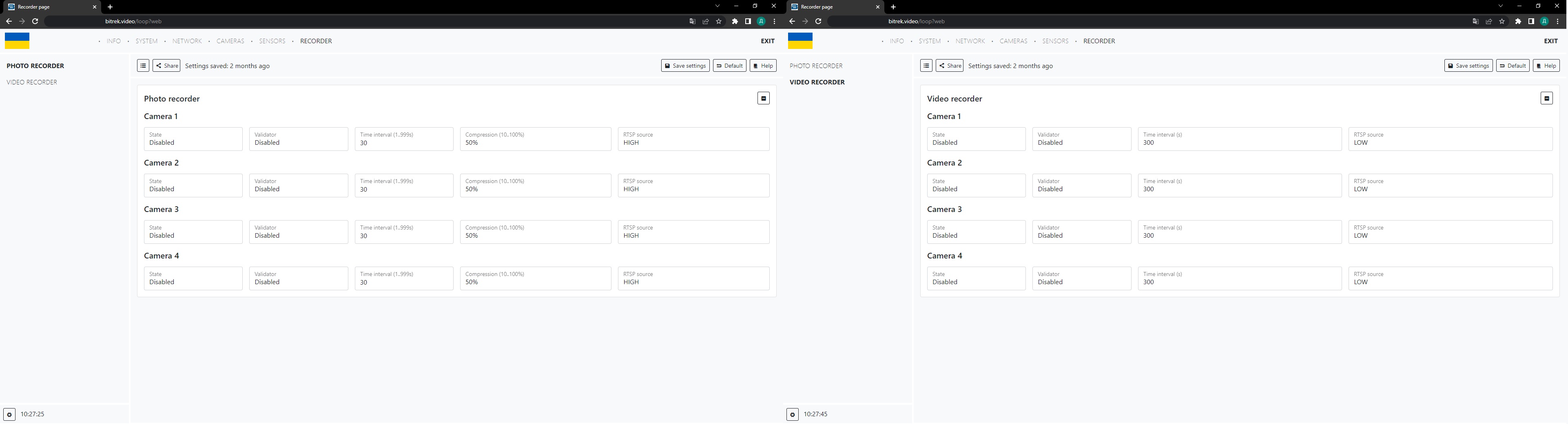
The section allows you to configure the device for photo and video registration
Camera settings
First you need to make sure that the camera is in good condition and connected to the device. If you have a Dahua camera, click the “Start Auto Init” button.
Note: Autoinit works only with Bitrek-Dahua cameras.

In most cases, autoinit will detect and add the camera for you, however, if this does not happen, you can try to add it manually by clicking the “Add” or “Advanced” button and specifying the desired parameters.
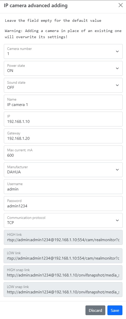
IMPORTANT! Do not forget to save settings by clicking the appropriate button.
Note: If after the performed operations the camera is not added try:
- Check the cable for serviceability;
- Check the connection (if the camera is connected, the diode at the connection point will blink green rapidly);
- Check the camera for proper operation
Live streaming settings
After connecting and configuring the camera, you can also set up a live broadcast. To do this, go to the appropriate tab, in the broadcast configuration section, enable the desired camera, and in the player, click on the menu on the side and select the desired camera to view the broadcast.
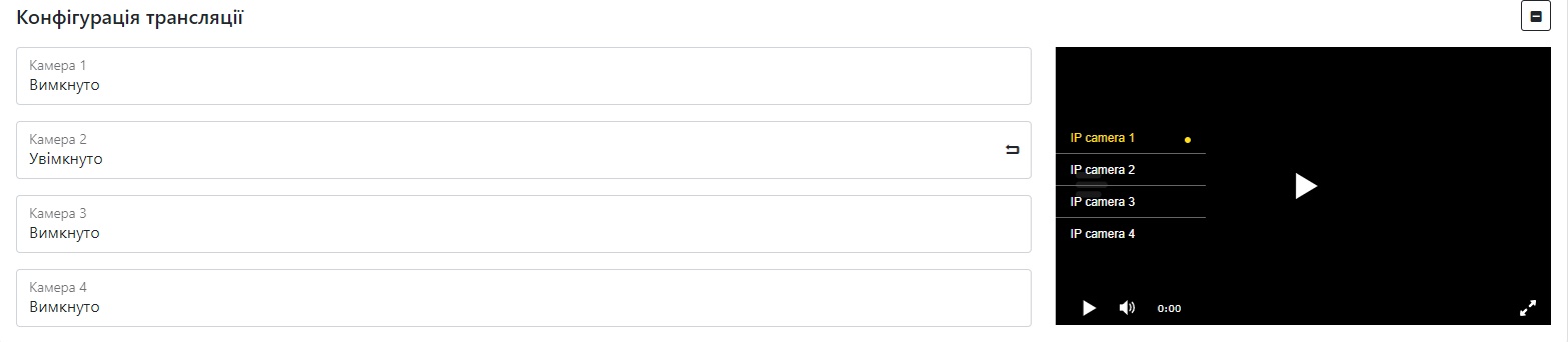 IMPORTANT! Do not forget to save the settings by clicking the corresponding button.
Note: You can also configure the streaming mode by selecting the type of stream (DASH, HLS) and the display quality (1 stream - better quality, 2 stream - worse quality) when using the free Bitrek VPN in the standard version uses 2 stream. To use 1 stream, please contact your service provider.
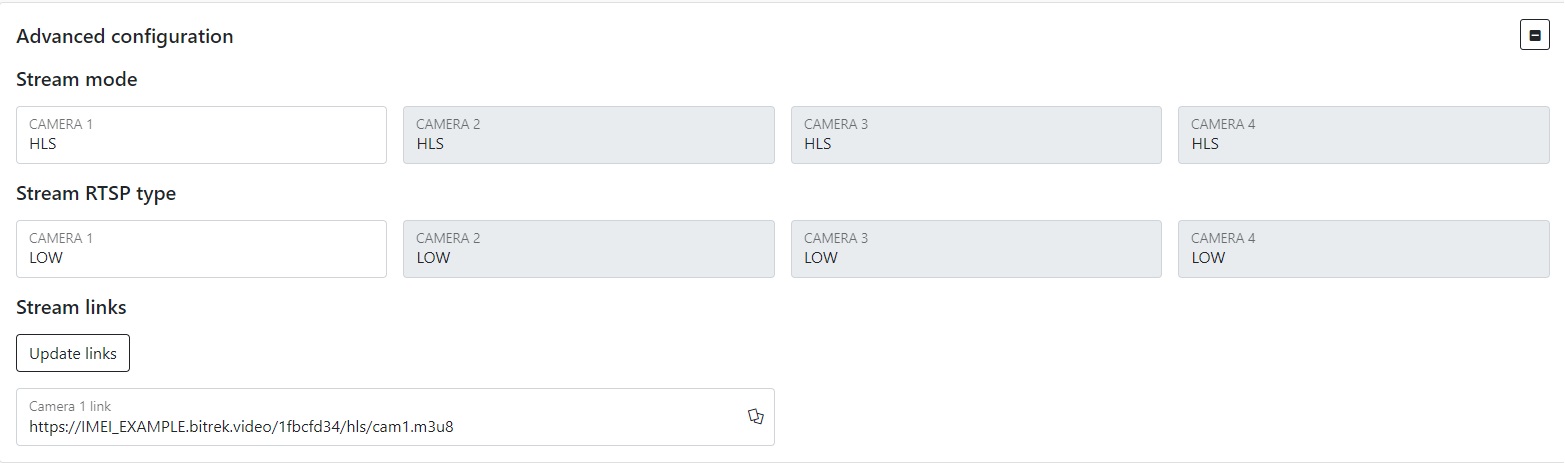
Note: After setting up the stream, you can also view the live stream in the control panel in the “STREAM VIDEO “ section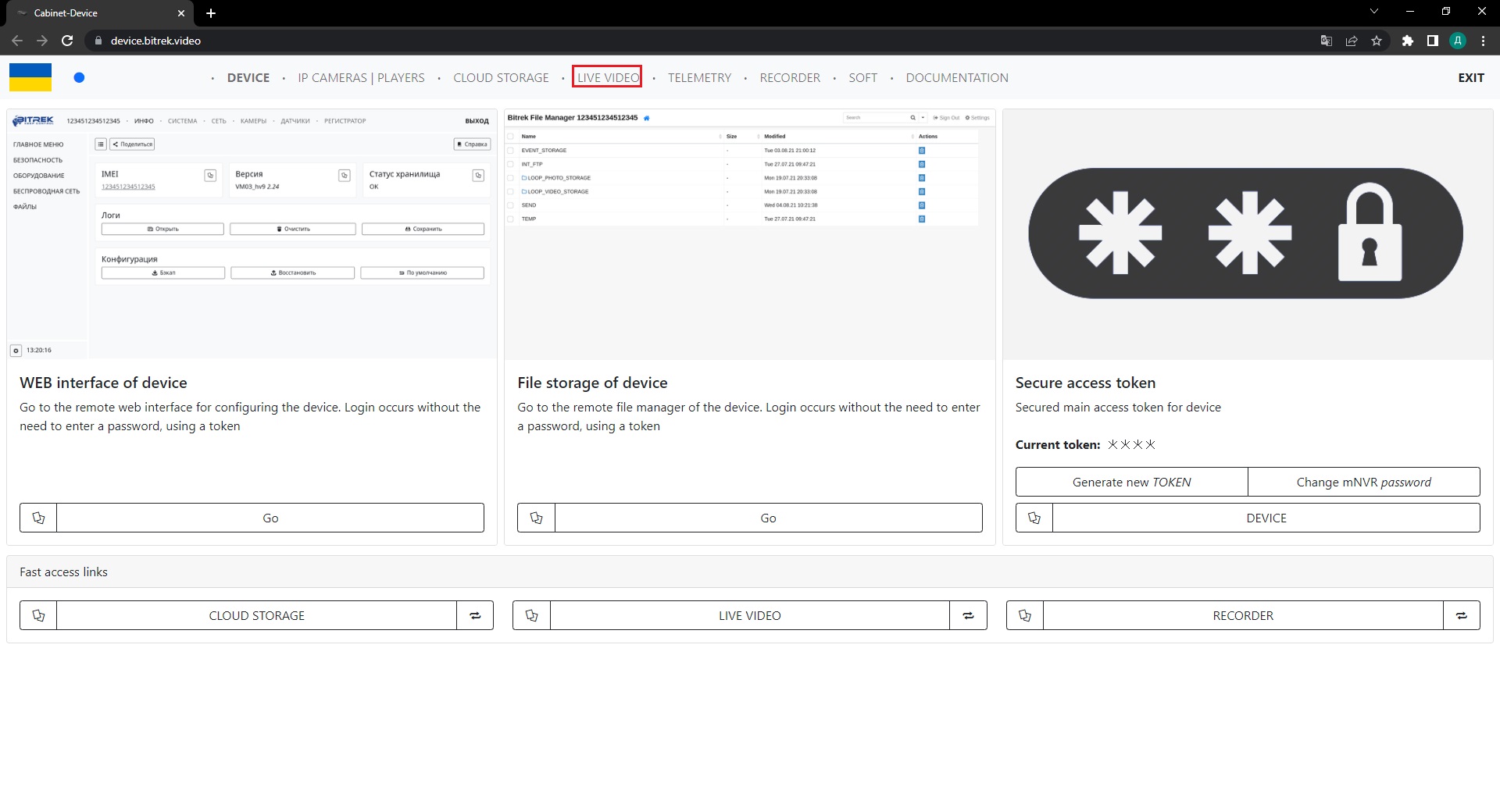
Setting up the recorder
After setting up the camera and sensors, you can also set up the photo and video recorder. To do this, you need to:
- Go to the appropriate tab;
- Turn on the required camera;
- Select the sensor validator;
- Set the shooting interval;
- Degree of compression (the higher the percentage, the better the quality);
- RTSP source (1 stream - higher quality, 2 stream - worse quality).
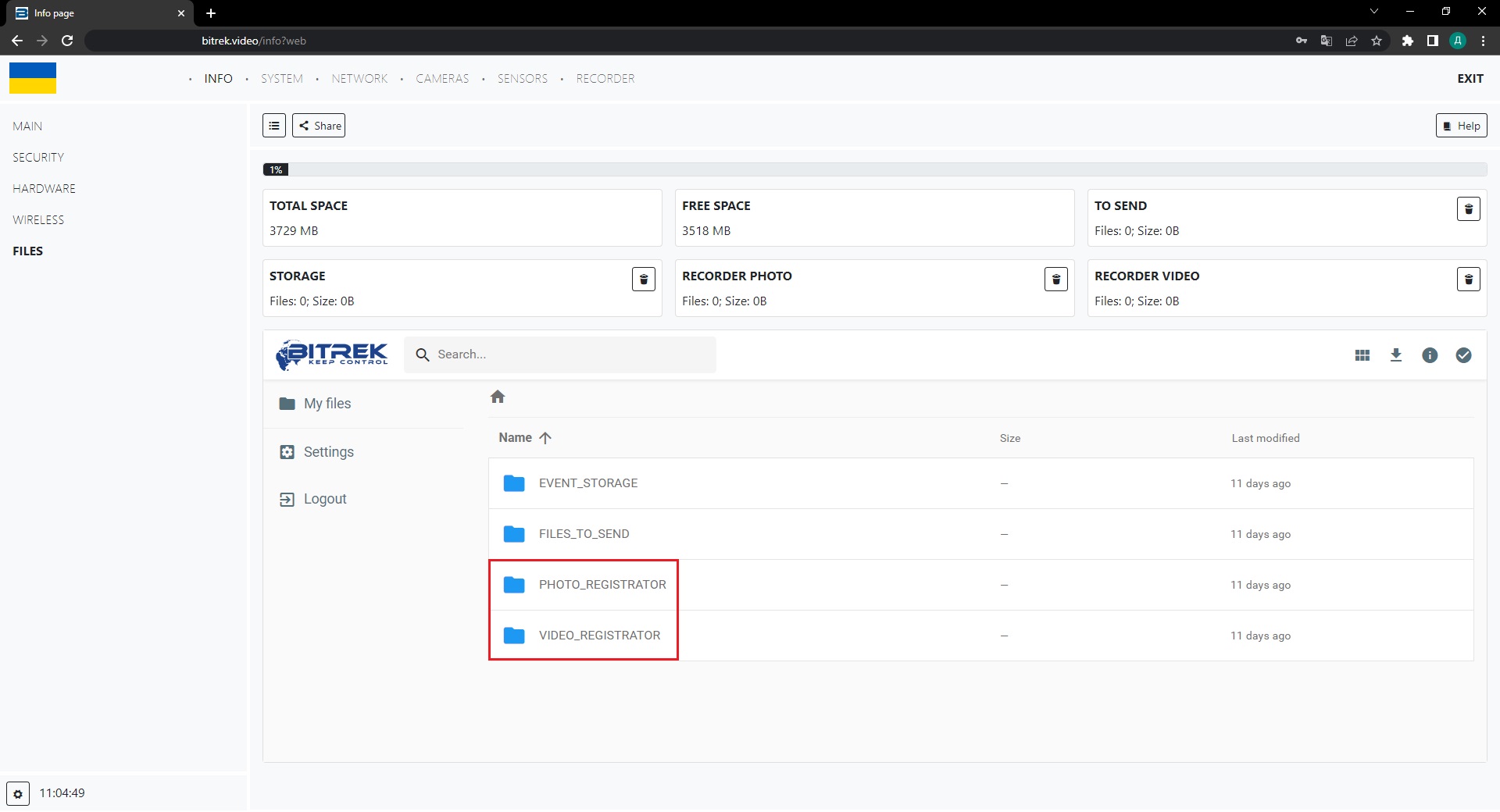
Note: Multimedia will be sent to the …_REGISTRATOR folder in the INFO/FILES section
Sensor settings
Tracker settings
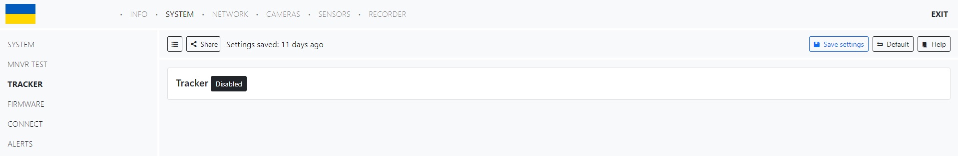
To configure the tracker, you need to go to the appropriate tab in the SYSTEM/Tracker section and turn on the tracker by clicking the corresponding button
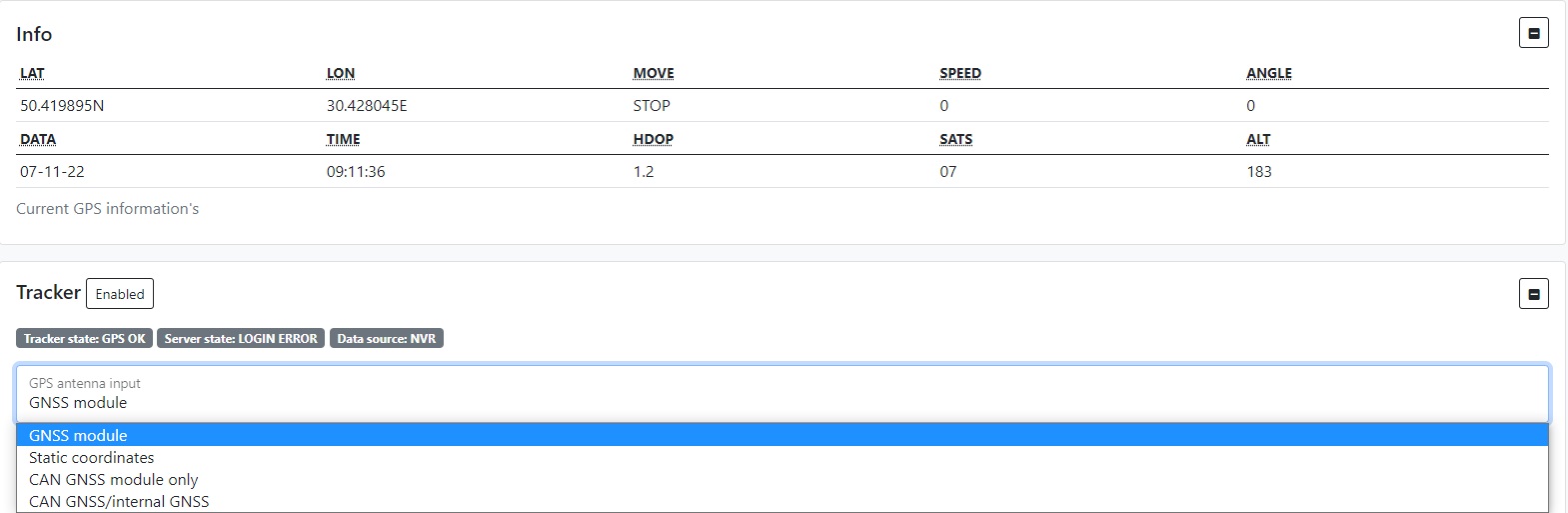
After that you will need to select the type of GPS antenna, now you can connect or set the GPS as follows:
- GNSS module
- Static coordinates
- CAN GNSS module
- CAN GNSS / internal GNSS
1) For GNSS module you just need to connect it to the device
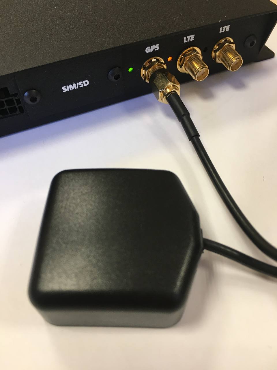
And in the drop-down list select GNSS module, the position determination will be automatic
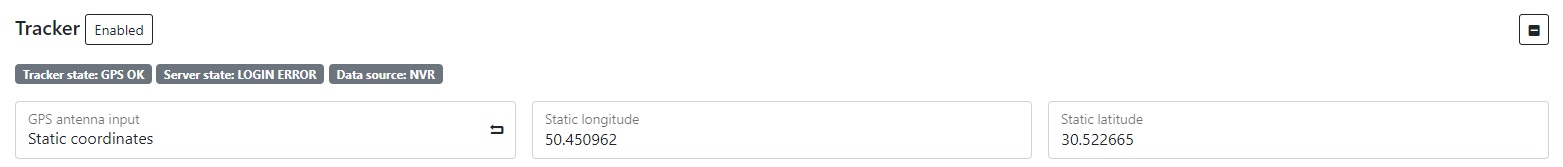
2) For static coordinates, select Static coordinates in the drop-down list and enter the coordinates manually
3) For CAN GNSS you need to connect the module via CAN, select the device that you connected in the list and specify its address
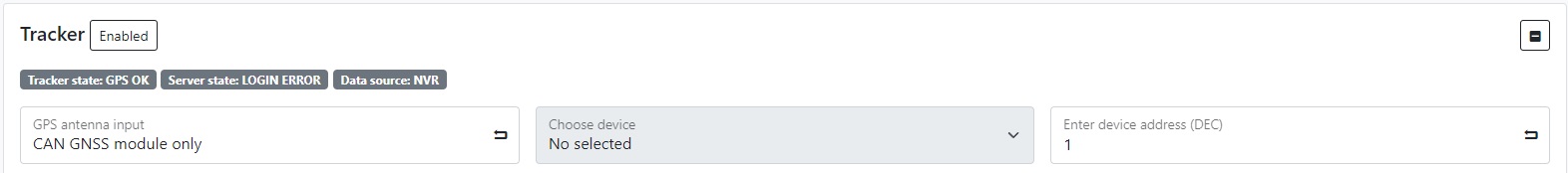
4) For CAN GNSS / internal GNSS, the situation is the same as in step 3
After successful configuration of the module in the Info tab you can see the current GPS information about your location
When configuring the GPS module, you can also configure the following options for it:
- Sending photos via IPS
- Sending links via IPS
- Pre-configure video link
- Link to video
- QR code recognition
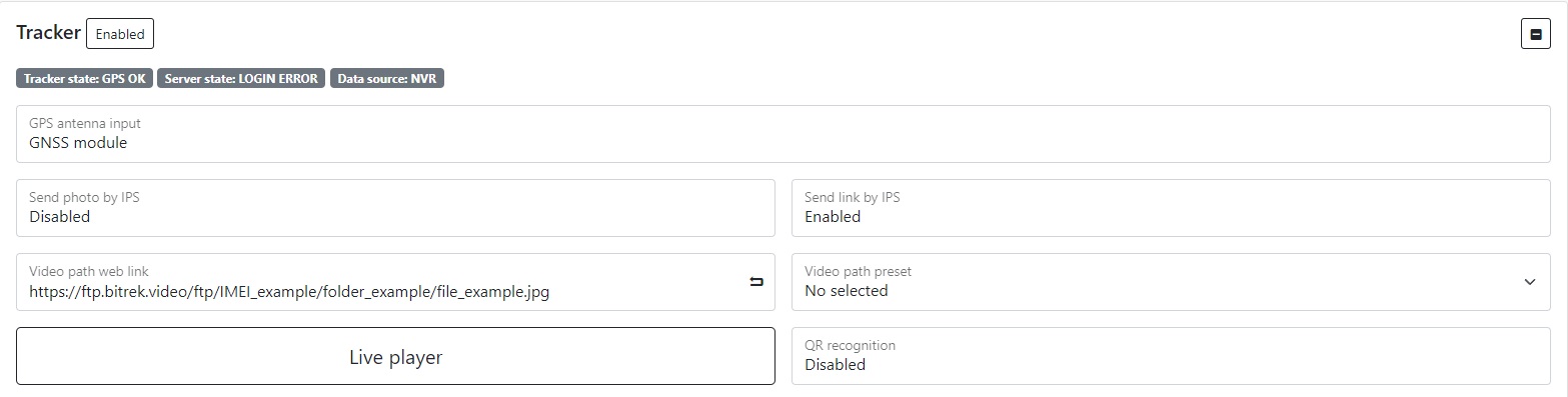
We recommend using the default format that is installed in the standard firmware (photo above)
Send photos via IPS - enable/disable the function of sending files to your IPS server Send links via IPS - enable/disable the function of sending files to your IPS server using a link
Note: We recommend sending only links, because separately photos are also sent to FTP, as a result of which they are duplicated, to avoid this, free up memory and not load the device unnecessarily, we recommend leaving these options by default.
Presetting the link to the video - if you have paid for FTP access, you can select the server to which you can go by specifying the link to the video in the appropriate field (you need to specify the server address, device ID, file package and its name, for example: https://ftp.bitrek.video/ftp/IMEI/IMEI/file_example.jpg
Recognition of QR codes - we recommend leaving this option disabled if you do not use it
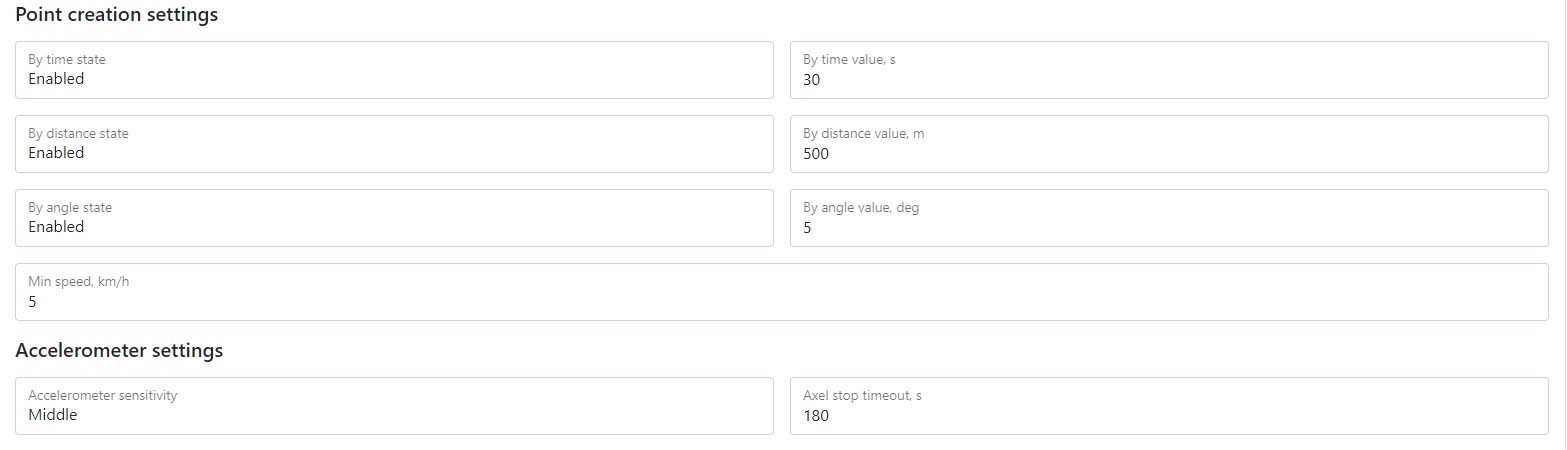
Setting up point creation
You can configure the creation of points for the track of your vehicle using parameters such as:
- Time
- Distance
- Angle
- Speed
Time - The point will be constantly created after the period of time that you set in the field “In time, s”
Distance - The point will be created after the vehicle has passed the distance that was specified in the “By distance, m” field
Angle - The point will be created after the vehicle turns the angle that was specified in the “By angle, deg” field
Speed - The minimum speed value at which the construction of points will start, if the value is less than the specified one, the device will switch to the parking mode
Setting the sensitivity of the motion sensor
You can configure the sensitivity of motion, which depends on the position of the device, for example, if the device will shake a lot - it is recommended to set a low sensitivity, if it will be almost motionless, then vice versa high
Stop timeout - the time at which the vehicle can stand and the track of points is not reset (for example, when the vehicle is at a traffic light)
Configuring the IPS server
You can configure the IPS server to send telemetry to services such as Wialon and others.
To do this, enter the new server in the field:
- IP address
- Port
- ID
- Password
- Timeout
If you also have a backup server, you need to enable it in the corresponding menu and specify the address and port. If there is no connection with the main server for more than you set in the Timeout field, the data will be sent to the backup server
Note: Do not forget to save settings by clicking the appropriate button!
LAN settings
To connect the device to a LAN network, you must first connect the device via LAN cable from the router
Then go to the NETWORK/LAN tab where you can select the network type:
- Automatic(DHCP)
- Or set it manually (static) by entering the IP address of the device, subnet mask, gateway, and internal DCHP state (turn off if you connect a router that has its own DHCP server)

Storage settings (FTP)
You can save space on your device by sending data to the server. To do this, go to the NETWORK/FTP section and enable the required server from the list. There are three types in total:
- FTP event server for sending files that will be sent to your device if some event occurs (for example, if your sensor is configured for it);
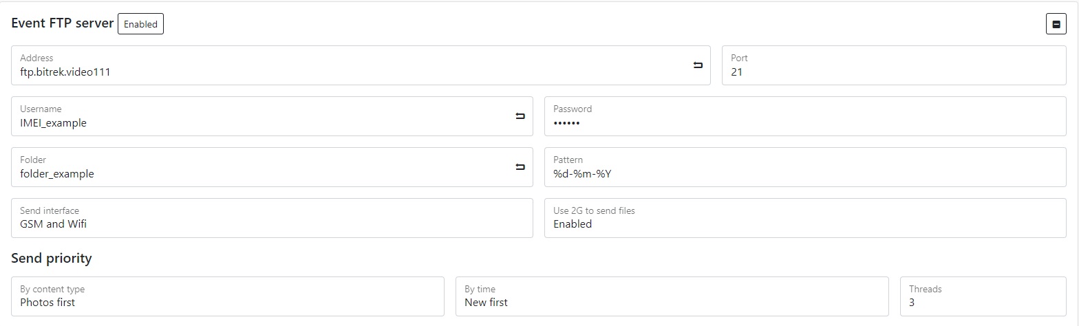
- FTP server for the photo recorder to send photos that will be captured by your pre-configured photo recorder;

- FTP server for video recorder to send videos that will be recorded by your pre-configured video recorder.

You can adjust your server settings using the appropriate parameters:
- Setting address and specifying port to which your media data will be sent;
- Create folder to which files will be sent;
- Select the network type in which the data will be sent (via Wi-Fi, if you want to save SIM card traffic or you do not have it installed, or GSM data (if a SIM card is installed));
- If a SIM card is installed, you can also enable the use of 2G for sending files, this will ensure sending files in places with poor connection, while the download speed will be slower and the time will be shorter. Please take this into account when setting up the server;
- Set the priority of sending files by time (older files first or vice versa).
Please note: the speed of data download depends on the quality of the network in which the device is located, the worse the signal quality, the more time it will take to send files. Please take this into account when setting up the server.
Note: Do not forget to save settings by clicking the appropriate button.
GSM network settings
There are several GSM settings on the device:
- GSM/LTE traffic;
- GSM/LTE configuration;
- SMS/USSD configuration.
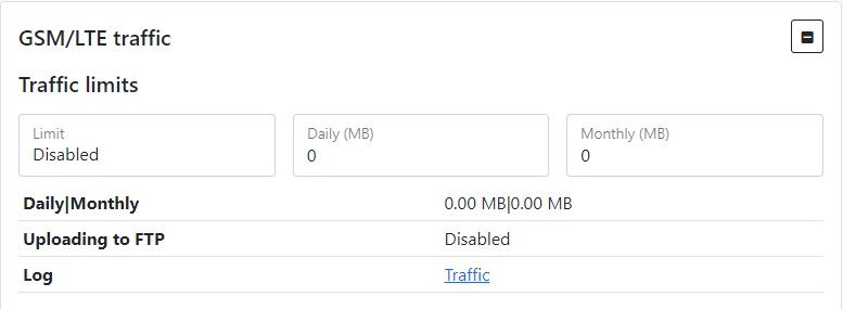
GSM/LTE traffic settings
You can configure the traffic limit on the device to save it, for this you need to go to the NETWORK/GSM tab, enable the limit using the corresponding button and set a limit for the use of traffic by the device per day or per month.
The example shows a traffic limit of no more than 2GB per day and 65GB per month

Note: do not forget to save settings by clicking the appropriate button.
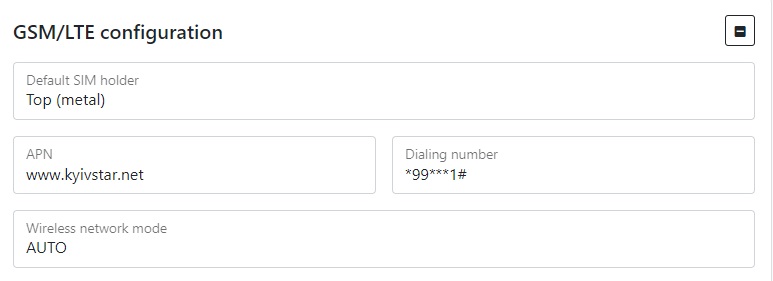
GSM/LTE configuration
You can configure:
- SIM card position on the device top or bottom(depending on how you installed the SIM card)
- APN (by default www.kyivstar.net)
- Dialing number
- Network mode in which the device will work (by default, the network mode is set automatically, but you can set this parameter manually)
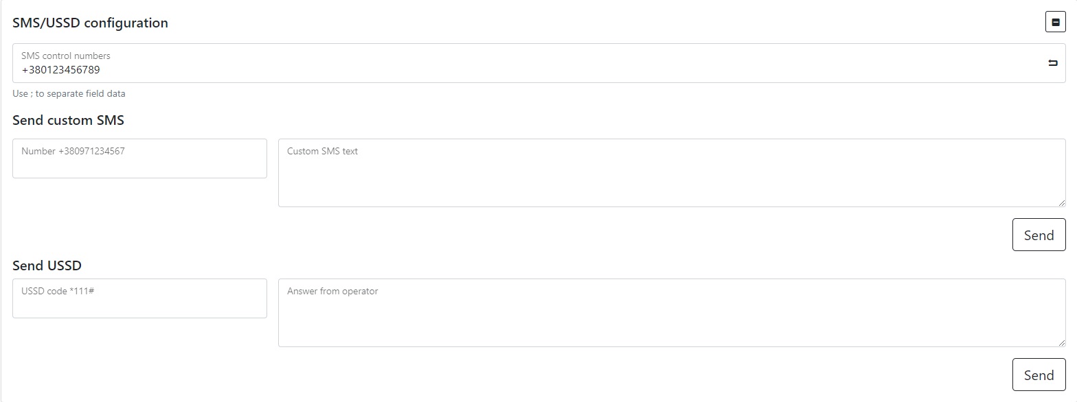
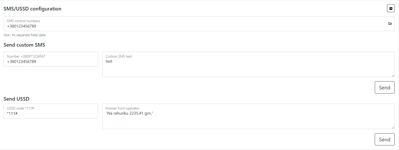
SMS/USSD configuration
The device allows you to configure sending SMS by the user for example to receive the number from which the SMS is sent. And send USSD codes for example *111# to check the account on the SIM card.
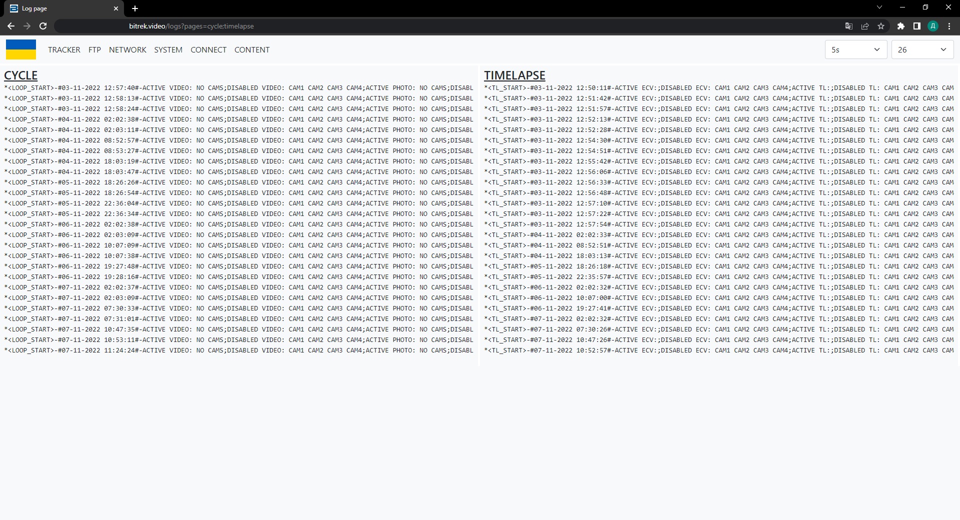
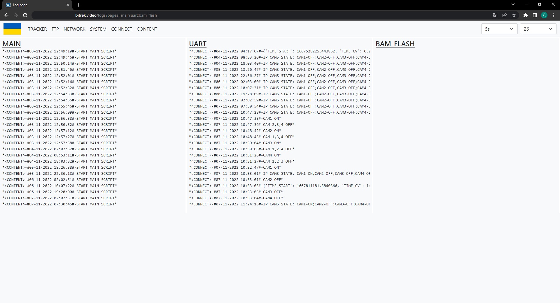
View logs
mNVR provides the ability to view logs on the device to diagnose problems. To do this, go to the tab “INFO/LOGS/OPEN”

In the window that opens, you need to select the desired section and click on it
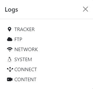
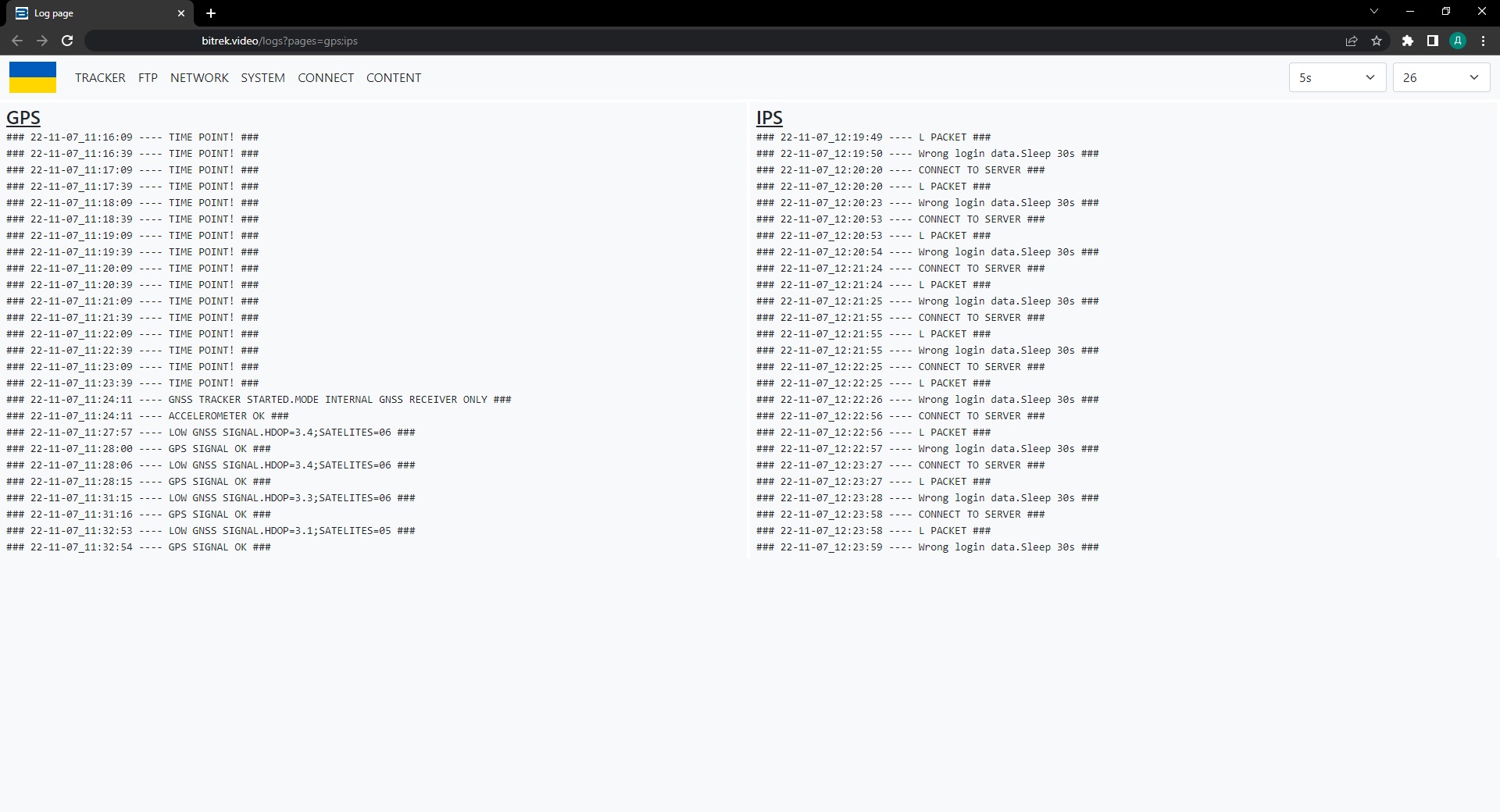
TRACKER
The GPS section contains information about your GPS tracker
The IPS section contains information about the status of your IPS server
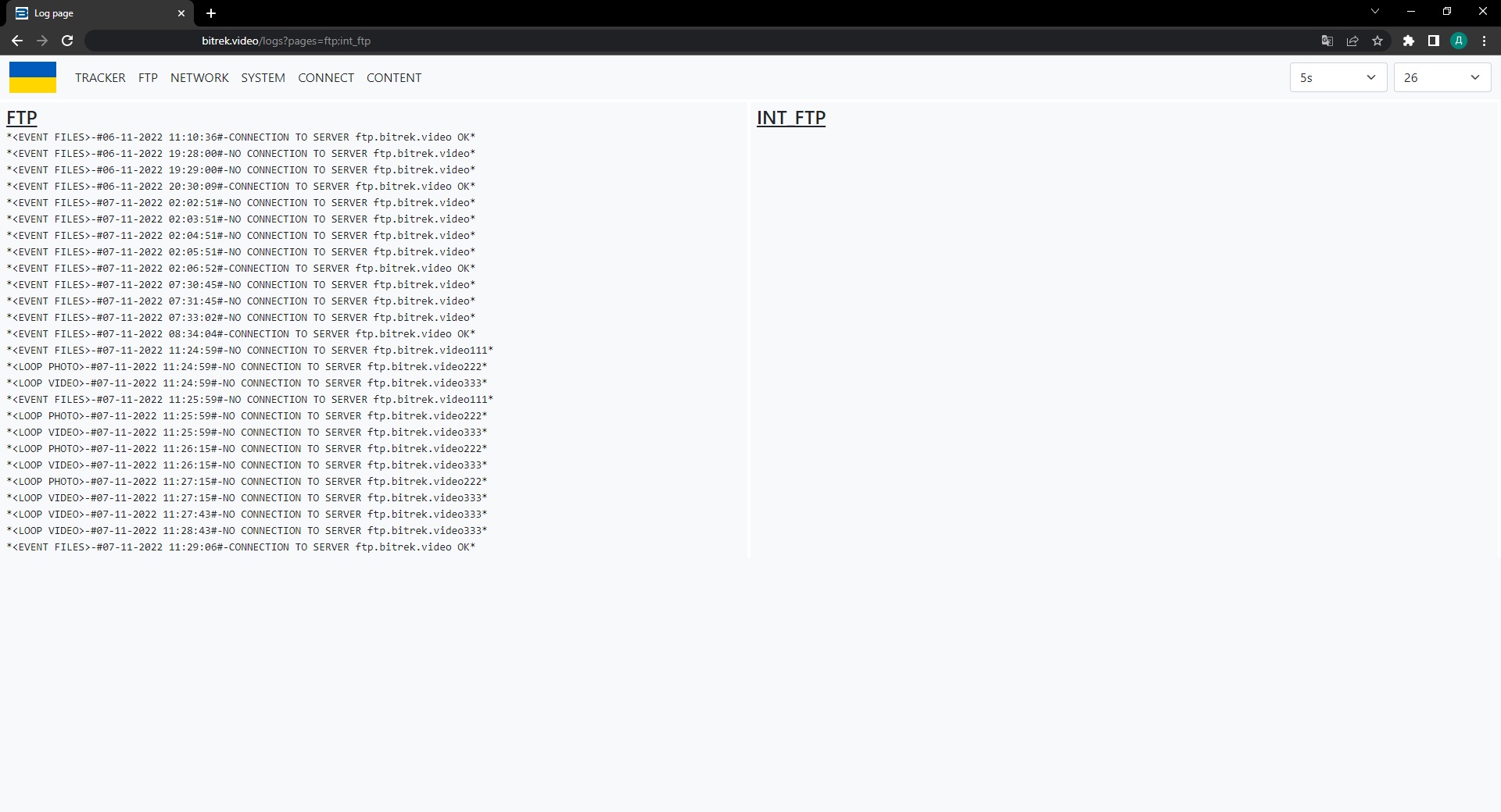
FTP
In section FTP information about the status of connection to the FTP server
In the INT FTP section, information about the status of your internal storage (SD card, SSD drive, etc.)
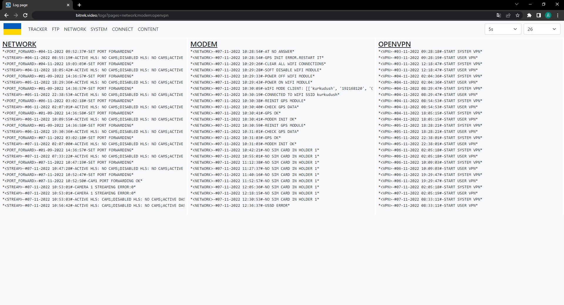
NETWORK
In section NETWORK information about the status of devices that can be connected: cameras, etc.
In the MODEM section you can see the status of your modem, such as the status of connection to Wi-Fi, LAN network, or SIM card status
In the OPEN VPN section you can see the status of your VPN server
SYSTEM
The STARTUP section shows the success status of the system boot, file system check, etc.
Section SETTINGS checks all functions of your device (WIFI, VPN, VPN, GSM, tracker, cameras, etc.)
SCRIPT ERRORS errors that may occur when setting up the device

CONNECT
The MAIN section checks the health of the main CONNECT system script
Section UART checks the health of devices and cameras connected via UART
BAM FLASH shows the progress of the tracker firmware using BAM
CONTENT
Section CYCLE shows the progress of camera recording in loop mode
Section TIMELAPSE shows the progress of recording cameras in time-lapse mode