Table of Contents
Installation Recommendations
This section will cover tips on topics such as:
- Unplugging the RJ45 connector
- Unplugging cables that come with the Bi-mNVR device
- Unplugging Bi-mNVR connectors
- Bi-mNVR antennas connection
- Installation highlights
Unplugging the RJ45 connector
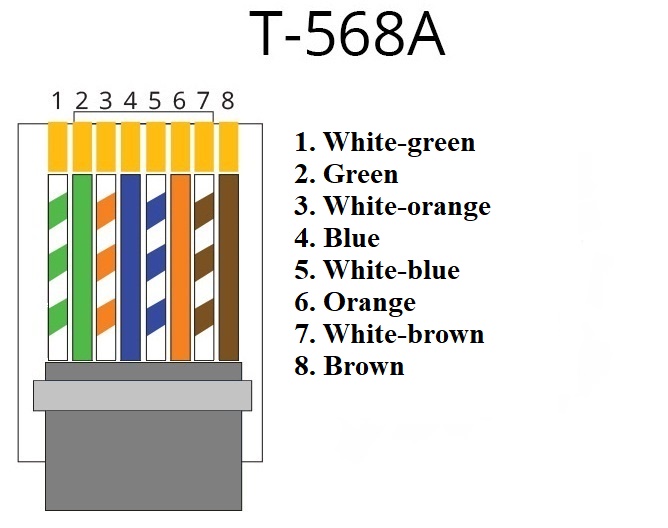
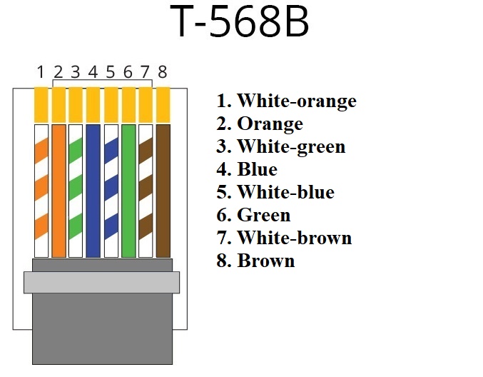
There are two ways to pin-up the RJ45 connector: T-568A and T-568B, the pin-up type has no effect on the data rate, so choose the one you like best. We use the T-568B.
How to crimp an 8 wire twisted pair
We need a crimper, an RJ45 connector and a twisted pair, and scissors.
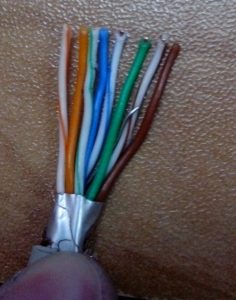
Step 1: Cut the upper sheath at the end of the cable about 2.5 cm from the edge. Next, unwind the twisted wires and take out the excess
Step 2: Clamp the wires between your fingers and line them up. Sort them out as shown in the pictures above
Step 3: Shorten the wires so that the wires peek out about 1.5 cm from the edge of the insulation. Use scissors to make a straight cut across all the wires.
Step 4: Carefully insert all 8 wires into the RJ45 connector as far as possible, and make sure they stay aligned and each color goes into the appropriate channel
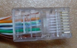
Step 5: Insert the wires all the way into the RJ45 connector, checking the wire sequence. Then insert the connector into the “P8” socket in the crimper and crimp the connector until you hear it click into place
Bi-mNVR device pin assignment
- RJ45 connectors, type T568B
| No. | Name | Signal type | Pin assignment |
|---|---|---|---|
| 1 | white-orange | signal | TX+ |
| 2 | orange | signal | TX- |
| 3 | white-green | signal | RX+ |
| 4 | blue | power | +CAM_PWR |
| 5 | white-blue | power | +CAM_PWR |
| 6 | Green | signal | RX- |
| 7 | brown-white | power supply | GND |
| 8 | brown | power | GND |
- CONNECT-BUS connectors
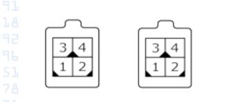
No. ^ Name ^ Signal type ^ Pin assignment ^
| 1 | GND | power | common wire (ground) |
| 2 | CAN L | Input/Output | CAN_L bus signal |
| 3 | + Vin | Power | '+' on-board power supply |
| 4 | CAN H | Input/Output | CAN_H bus signal |
*CAN port connector
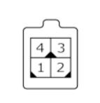
| No. | Name | Signal type | Pin assignment |
|---|---|---|---|
| 1 | GND | power | common wire (ground) |
| 2 | TX | Input/Output | Signal 'TX' extension port |
| 3 | + 3.3V | supply | 3.3V power output |
| 4 | RX | Input/Output | 'RX' signal of the expansion port |
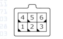
| No. | Name | Signal type | Pin assignment |
|---|---|---|---|
| 1 | Dat_low 1 | Input | Discrete input with active '0' |
| 2 | Dat_high 1 | Input | discrete input with active '1' #1 |
| 3 | + 3.3V | input | analog input |
| 4 | GND | power supply | common wire (ground) |
| 5 | Dat_high 1 | input | discrete input with active '0' no.2. reserved for the ignition signal |
| 6 | GND | power supply | common wire (ground) |
General guidelines
Operating conditions
- ambient temperature from -30°C to +80°C
- Relative humidity up to 80% at +30°C
- atmospheric pressure between 84 kPa and 107 kPa (630 - 800 mm Hg)
installation recommendations
- The device location area should allow for plugging in the connector, excluding the case of its damage, as well as exposure to direct sunlight and moisture
- Recommended mounting location in the vehicle: Under the dashboard, level
Additional conditions
- During welding work and vehicle repair it is obligatory to disconnect power connector and peripherals from the device
- Power supply voltage must not exceed 36V. Failure to observe this condition could render the unit inoperable
Transport and storage conditions
- The device can be transported in the manufacturer's transport package by all kinds of closed ground and sea transport (in railway carriages, containers, closed cars, holds, etc.); transportation in sealed aircraft heater compartments is permissible.
- Transportation and storage must be carried out in conditions that meet the storage conditions according to GOST 15150-69
- Permissible level of shock loads: shocks with acceleration of 2-5g with impulse duration of 5-10 ms
- The air of the storage room must not contain aggressive impurities, dust, grease, moisture, exceeding the standards according to. GOST 12.1.005-88
Safety requirements for installation and maintenance work
- During work on device installation organizational and technical measures shall be taken, which shall ensure safety of work with measuring equipment, auxiliary equipment and consumables
- The responsibility for observing the safety measures rests with the technical personnel in charge of the device installation, as well as with the personnel in charge of the equipment at the site of the work.
- On-site compliance with fire safety rules in accordance with GOST 12.1.004 and electrical safety in accordance with GOST 12.1.019
- In road transport at the place of work, it is necessary to comply with the requirements of labor safety regulations in accordance with DNAOP 0.00-1.28-97
- It is recommended to store the unit in shockproof packaging to avoid damage.
- Before dismantling the unit, the power supply must be switched off.
- Do not install or remove the SIM card while the device is powered